Method of inspecting insulators to detect defects

a technology of insulator and inspection method, which is applied in the manufacture of sparking plugs, instruments, sparking plugs, etc., can solve the problems of prior art insulator defect inspection method, limit the value of high voltage which can be used in such an inspection method, and difficulty in ensuring that insulators can be tested for providing a very high degree of electrical insulation

Inactive Publication Date: 2004-03-18
DENSO CORP
View PDF8 Cites 19 Cited by
  • Summary
  • Abstract
  • Description
  • Claims
  • Application Information

AI Technical Summary

Benefits of technology

[0010] It is a further objective to provide an insulator defect inspection method whereby it is not necessary for an insulator defect inspection apparatus to be provided with a rotation apparatus for individually rotating each of respective insulators which are to be inspected.
[0011] It is a further objective to provide an insulator defect inspection method whereby a wide range of positions in an insulator can be effectively inspected for defects.

Problems solved by technology

However when a high value of potential difference is established between the first and second electrodes for producing such spark discharges, if the potential difference is excessively high then the discharges may occur along other paths, i.e., passing through metal portions of the inspection apparatus.
For that reason, there are limitations on the values of high voltage which can be used in such an inspection method.
Hence, it is difficult to ensure that insulators can be tested for providing a very high degree of electrical insulation.
This is a basic disadvantage of such a prior art insulator defect inspection method.
Furthermore, due to the fact that the tip of the first electrode is located at one specific position within the aperture in the insulator that is being inspected, and any by-passing of the spark discharges (due to current flowing through a defect region in the insulator) will take place along a path between the respective tips of the first and second electrodes, the range of positions in the insulator which are effectively inspected by such a method is limited.
As a result, it is unnecessary to rotate the insulator which is being inspected, in order to examine the entire periphery of the insulator, so that it becomes unnecessary to provide a rotation apparatus for that purpose.

Method used


Image

  • Method of inspecting insulators to detect defects
  • Method of inspecting insulators to detect defects
  • Method of inspecting insulators to detect defects

Examples


Embodiment Construction

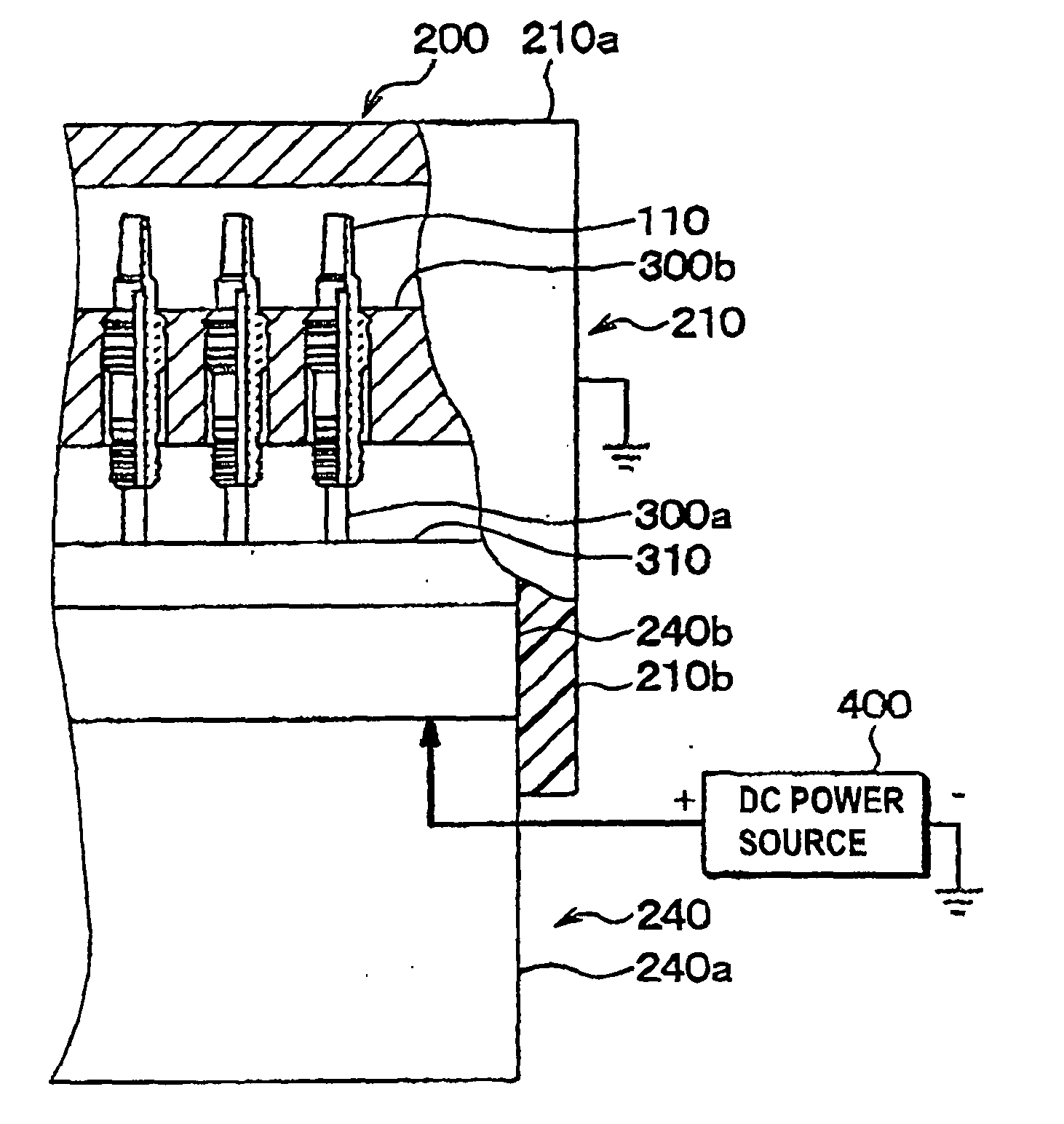
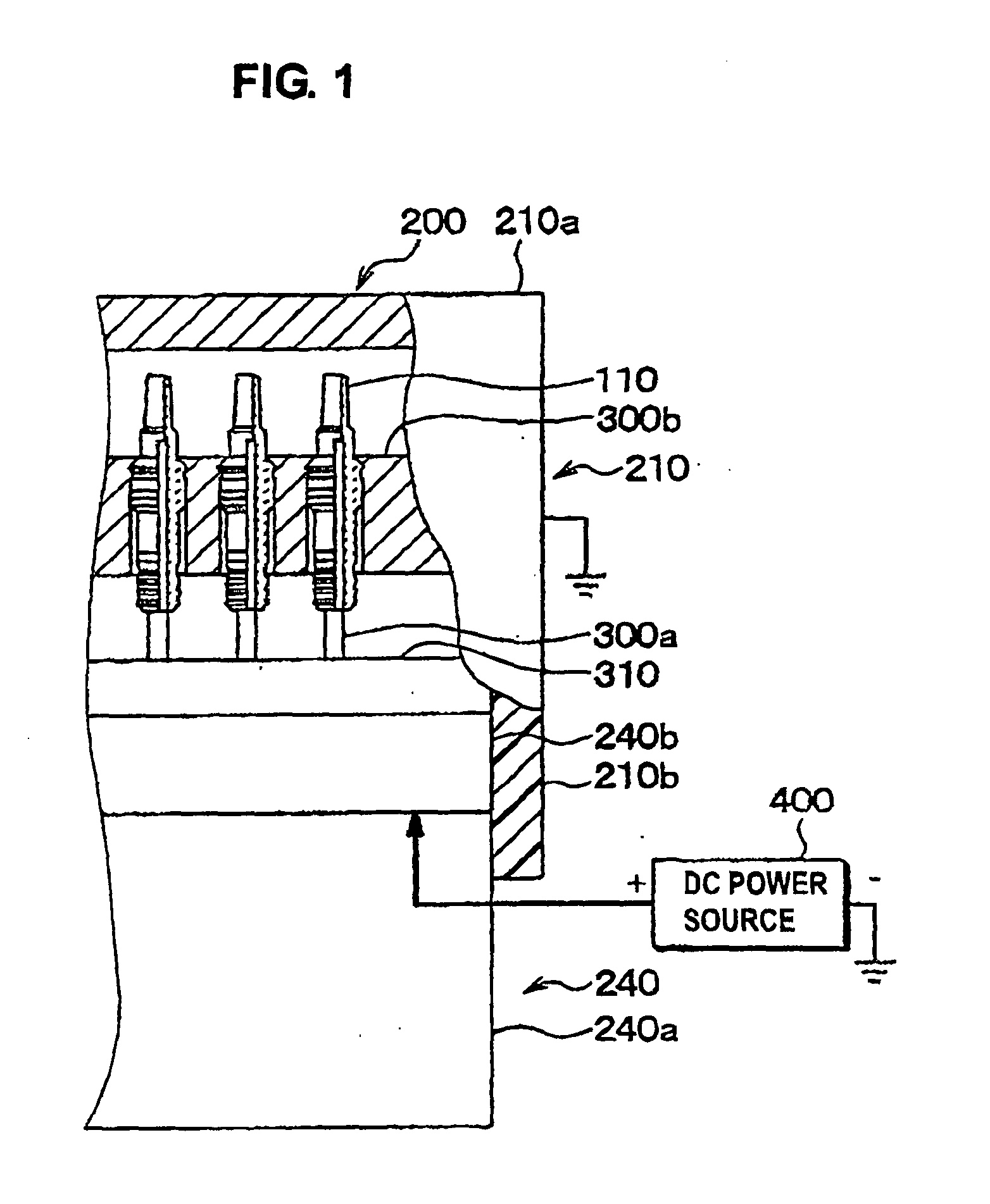
[0025] A first embodiment will be described referring to FIG. 1. This embodiment is applicable to the inspection of spark plugs for use in an internal combustion engine. A plurality of insulators are inspected as a single batch, concurrently, in a single inspection operation. In FIG. 1, the cross-hatched regions indicate cross-sectional areas. The inspection is performed within the interior of a pressure-proof chamber 200, which is filled with air under a higher pressure than atmospheric pressure. The pressure-proof chamber 200 is formed of a supporting portion 240 in conjunction with an upper movable portion 210, which can be raised and lowered by a slide mechanism (not shown in the drawings).

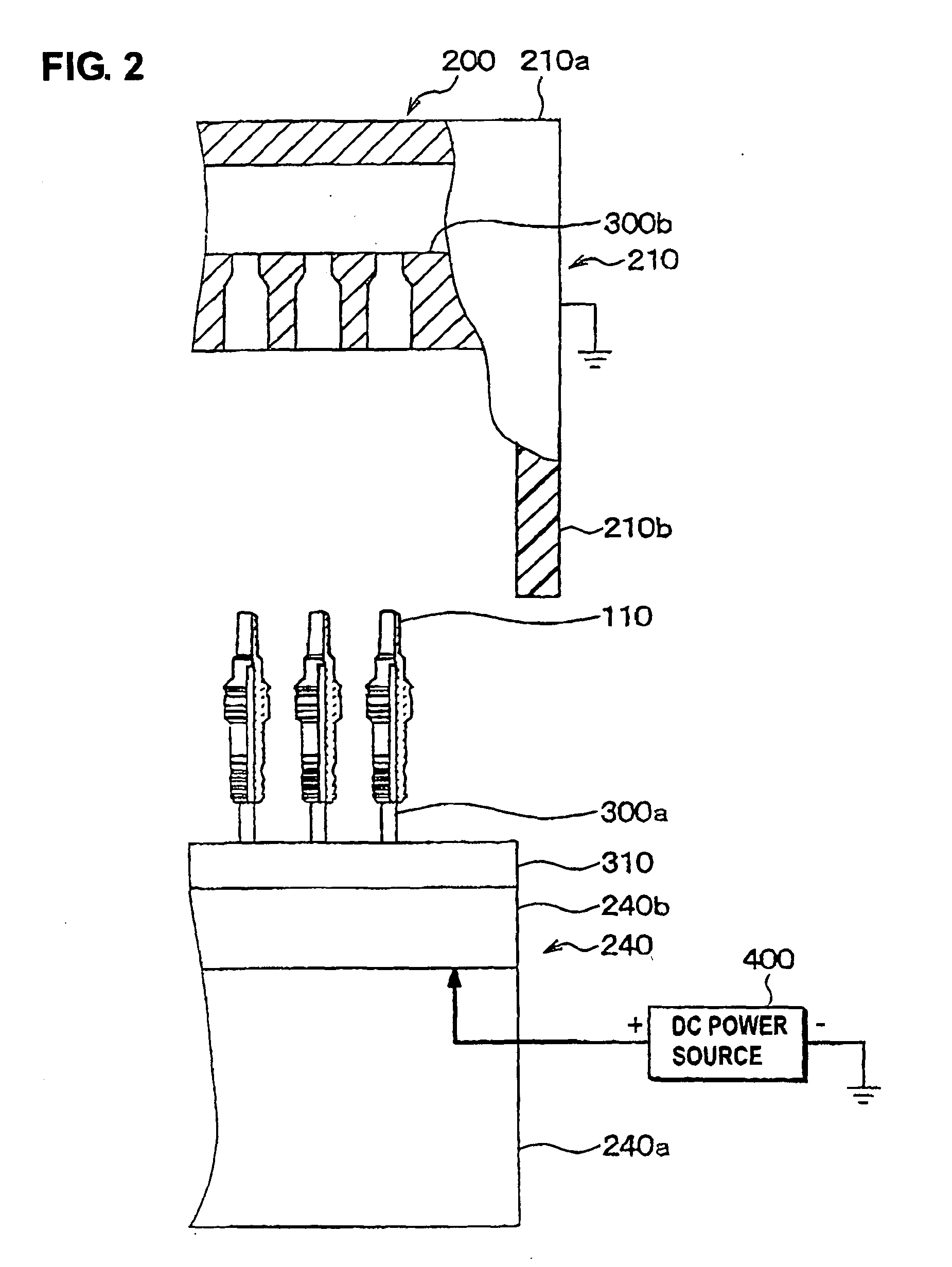
[0026] FIG. 2 shows the upper movable portion 210 raised to its highest position. Exchanging of a batch of insulators that have been inspected, for a new batch, is performed with the apparatus in the condition shown in FIG. 2.

[0027] The supporting portion 240 is formed of a support stage 240a,...


PUM

PropertyMeasurementUnit
pressureaaaaaaaaaa
output voltageaaaaaaaaaa
pressureaaaaaaaaaa

Abstract

A method of inspecting insulators such as spark plug insulators for defects, whereby a plurality of insulators are inspected concurrently by being disposed with a plurality of first electrodes engaged in respective apertures in the insulators, and with apertures formed in a second electrode being disposed to peripherally enclose respective insulators. With the insulators and electrodes set in a closed chamber under high air pressure, and high voltage applied between the first and second electrodes, any defect is detected based on a level of leakage current which then flows.

Description

[0001] 1. Field of Application[0002] The present invention relates to a method of inspecting insulators to detect defects. The term "insulator" as used herein, unless otherwise indicated, signifies a solid electrically insulating member, such as the insulator portion of a spark plug of an internal combustion engine. It is assumed in the following that each insulator which is to be inspected has an aperture formed therein, such as the central aperture which extends axially through a spark plug insulator.[0003] 2. Description of Prior Art[0004] A prior art method of insulator defect detection is known whereby a first electrode which is needle-shaped is inserted into a central aperture of an insulator such as a spark plug insulators, and a second electrode which is also needle-shaped is disposed at a distance from the second electrode such that a spark discharge can occur between the first and second electrodes. A high voltage is then applied between the first and second electrodes whi...

Claims


Application Information

Patent Timeline
Patent Type & Authority Applications(United States)
IPC IPC(8): G01N27/20G01R31/12H01T13/20H01T13/58H01T21/02
CPCG01N27/205
Inventor HORI, KOJI
Owner DENSO CORP
Why Eureka
Try Eureka