Multipurpose hinge apparatus having automatic return function

a multi-purpose, hinge technology, applied in the direction of shock absorbers, domestic cooling devices, lighting and heating devices, etc., can solve the problems of reducing the durability of the hinge apparatus, the structure is complicated, and the assembly productivity deteriorates, and it is difficult to reduce the total length of the hinge apparatus

Inactive Publication Date: 2007-01-02
I ONE INNOTECH
View PDF7 Cites 32 Cited by
  • Summary
  • Abstract
  • Description
  • Claims
  • Application Information

AI Technical Summary

Benefits of technology

[0020]It is another object of the present invention to provide a multipurpose hinge apparatus having an automatic return function which can control automatic return speed and a return force of a door by changing a cam diagram angle of an ascending and descending guide hole which guides ascending of a piston, as well as which can control a restoring force of a return spring and an oil path of a hydraulic circuit during an automatic return of the door.
[0035]Also, the present invention can control return speed and a return force of a door simultaneously in multiple steps by adjusting an amount of flowing oil and a cam diagram angle of an ascending and descending guide hole, to thereby make the door automatically closed, and to thereby also temporarily stop the door which is opened at a certain angle by a pattern of the cam diagram angle.

Problems solved by technology

Accordingly, when the movable hinge knuckles receive big load and rotate for a long time, durability of the hinge apparatus is lowered and the structure is complicated.
As a result, an assembly productivity deteriorates.
Also, since the compression spring for performing an automatic return of the door is arranged in the upper side of the conversion head, and a hydraulic circuit for adjusting return speed of the door is arranged in the lower side of the conversion head, it is difficult to reduce the total length of the hinge apparatus.
Further, since lengthy space of arranging the compression spring is limited only in the upper side of the conversion head, a large restoring force cannot be provided for automatic return of the door.
Accordingly, it is difficult to apply the compression spring to a large-scale door.
As a result, it is not possible to apply the hinge apparatus to a structure that the center of a door differs from that of the hinge apparatus.
Accordingly, it is inconvenient for users to use the hinge apparatus.
Since the door opening and closing apparatus uses two combined door closers, it is difficult to make it compact.
In this case, since a fixing unit for temporarily fixing the door so that the door is not made to rotate at the state where the door is opened at a predetermined angle is not also installed in the hinge apparatus, it is inconvenient for users to use the hinge door opening and closing apparatus.
As a result, when a large external force such as a strong wind is applied to a door, it cannot prevent the door from being closed or opened at excessive speed.
However, in the case of the above-described hinge apparatus, the shapes and structures of the oil paths are very complicated, and thus workability is very bad.
Also, when the door is opened, it is temporarily stopped and when a large external force such as a strong wind is applied to the door, excessive speed of the door cannot be prevented.
Also, an oil containing space is deficient generally.
Meanwhile, the conventional art has not provided an optimized structure of an up / down rotational door hinge apparatus which is applied in a Kimchi refrigerator for use in a storage device for storing a fermentation food such as Kimchi which is one of Korean traditional foods.

Method used


Image

  • Multipurpose hinge apparatus having automatic return function
  • Multipurpose hinge apparatus having automatic return function
  • Multipurpose hinge apparatus having automatic return function

Examples


first embodiment

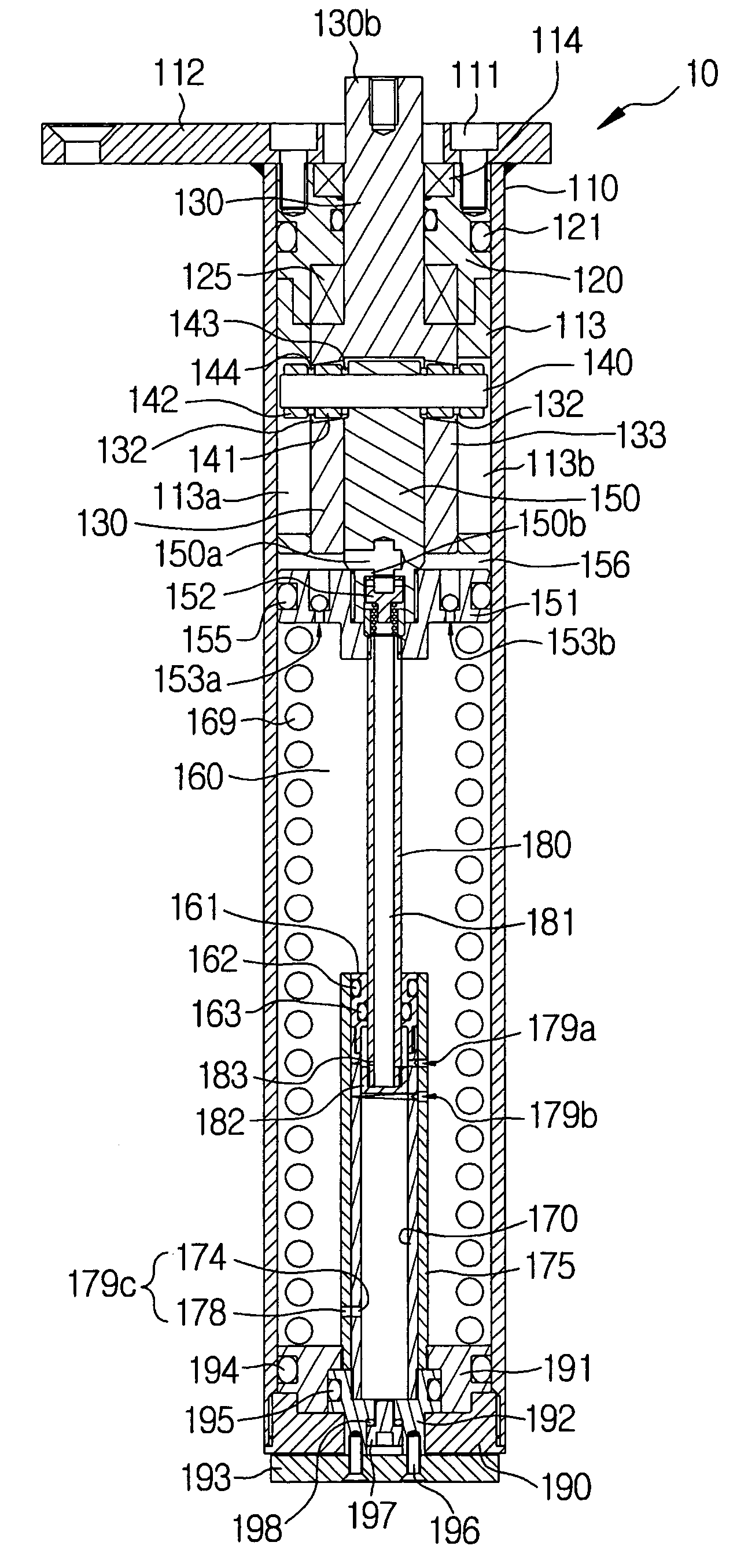
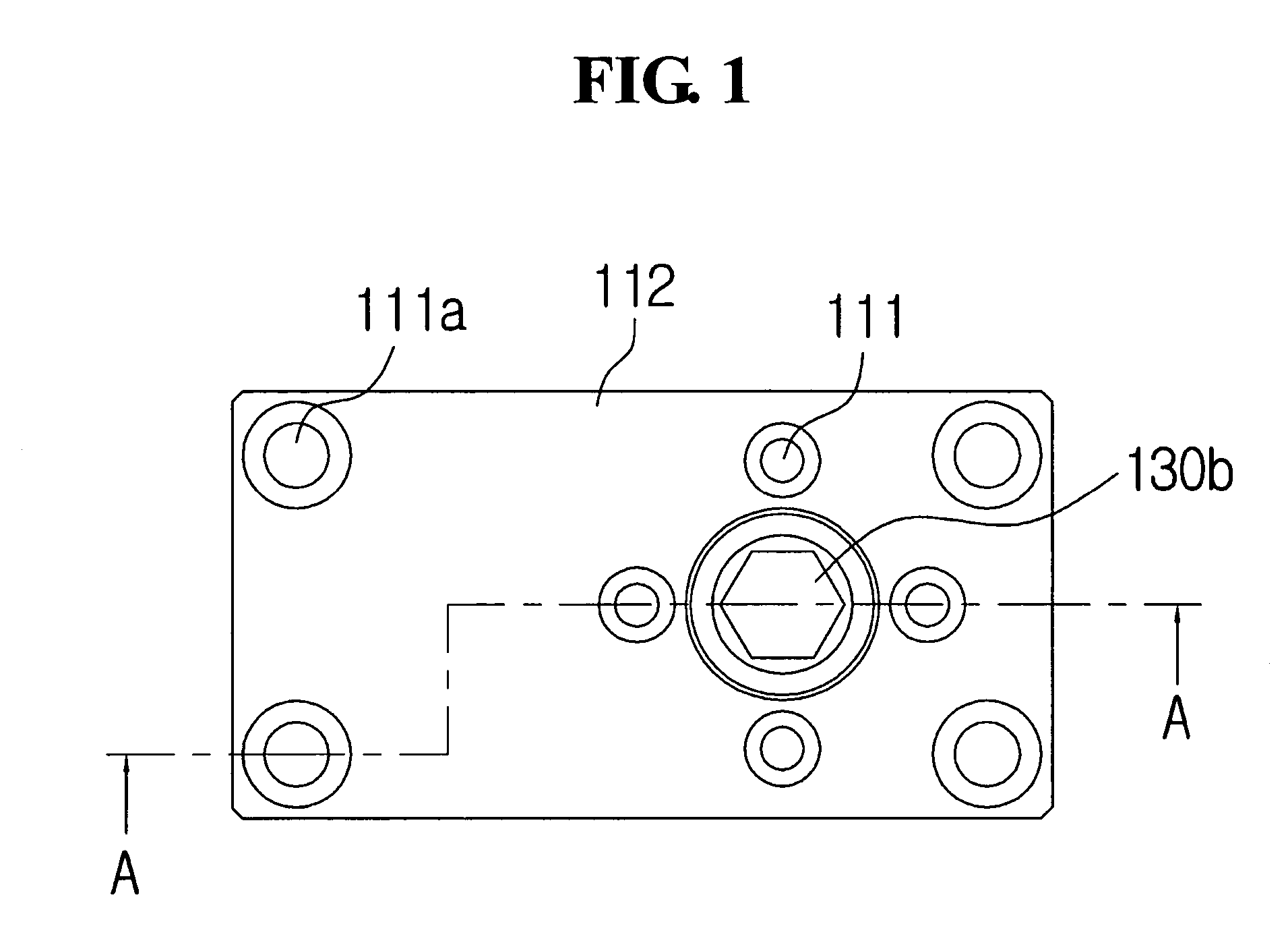
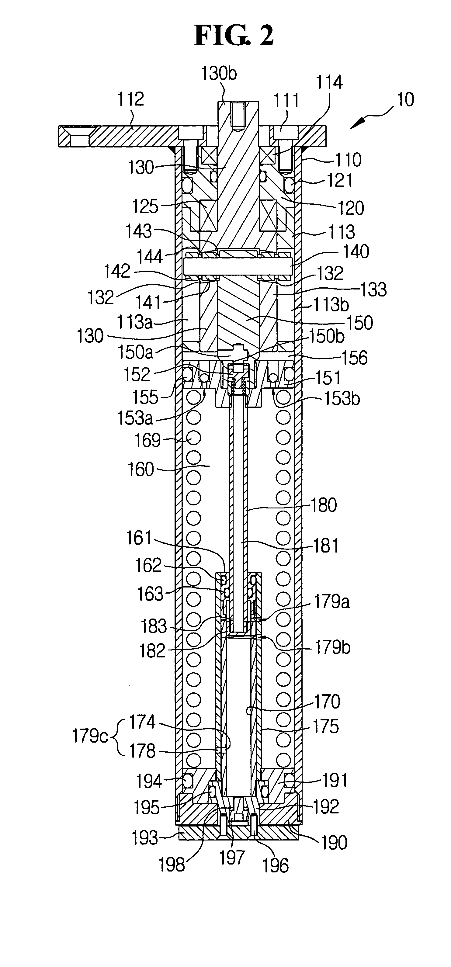
[0066]FIG. 1 is a plan view showing a multipurpose hinge apparatus according to the present invention. FIG. 2 is a lengthwise cross-sectional view cut along a line A—A of FIG. 1. FIG. 3 is a perspective view showing a vertical guide for vertically guiding a guide pin which moves up and down in the multipurpose hinge apparatus shown in FIG. 2. FIG. 4A is a perspective view showing a cam shaft for guiding a piston rod to move up and down according to opening and closing of a door in the multipurpose hinge apparatus shown in FIG. 2.

[0067]As shown in FIGS. 1 through 4A, a multipurpose hinge apparatus 10 according to the first embodiment of the present invention includes a cylindrical housing 110 accommodating internal elements. A cylindrical upper packing 120 is combined with the inner circumferential portion of the upper end of the cylindrical housing 110 in order to seal the upper end portion of the cylindrical housing 110. The inner circumferential portion of the housing 110, the axi...

second embodiment

[0159]In the second embodiment, it is needed that the inner circumferential surface of the cam shaft 130 and the outer circumferential surface of the piston rod 149 are proximate to contact each other in a sliding manner.

[0160]In the second embodiment, when the piston rod 149 ascends along the inner circumferential surface of the main body of the cam shaft 130 in association with ascending of the piston during a return of the door, the speed adjustment oil path 149a is closed according to the ascended height of the piston rod, that is, the door opening angle, an amount of oil flowing from the upper chamber 156 to the lower chamber 160 via the first oil path 150a and the overspeed prevention valve 152 is adjusted. As a result, the ascending speed of the piston 151 is adjusted in multiple steps, similarly to that of the first embodiment.

[0161]In the up / down opening and closing door hinge apparatus, a closing speed is reduced when the door is returned downwards by its own weight. Accor...

third embodiment

[0165]Meanwhile, FIG. 13 is an exploded perspective view showing a multipurpose hinge apparatus according to the present invention. FIG. 14 is a lengthwise cross-sectional view showing an assembly state of the multipurpose hinge apparatus shown in FIG. 13. FIG. 15 is an exploded perspective view showing a coupling relationship among a cam shaft, a piston rod, and a cam shaft guide in the multipurpose hinge apparatus shown in FIG. 14.

[0166]As shown in FIGS. 13 through 15, a multipurpose hinge apparatus according to the present invention includes a housing 210 accommodating internal components, a cam shaft 230 whose part is protruded upward from the housing 210 and which rotates by an external force, a guide pin 240 which moves along ascending and descending guide holes 232 which are formed on the outer circumference of the cam shaft 230 and vertical guide grooves 213 formed in the inner surface of the housing 210, a piston rod 250 which is connected with the guide pin 240 and moves u...


PUM


Abstract

A multipurpose hinge apparatus having an automatic return function is provided in which the apparatus is installed between the door and a main body. The apparatus includes a driving mechanism for ascending and descending a piston rod according to opening and closing of the door which is installed in the upper portion of a cylindrical housing. A piston is connected with the piston rod, in which a one-direction check valve is installed in the piston. The piston partitions an upper chamber and a lower chamber and ascends and descends in association with the piston rod. A first oil path communicates with the upper and lower chambers via the lower portion of the piston rod in the central portion of the piston. A compression spring which makes the piston ascend is inserted into the lower chamber. Oil is filled in the chamber. Thus, the hinge apparatus is automatically returned to the initial position with return speed in multiple steps by controlling an amount of oil flowing from upper chamber to lower chamber in multiple steps when a door is closed.

Description

BACKGROUND OF THE INVENTION[0001]1. Field of the Invention[0002]The present invention relates to a multipurpose hinge apparatus having an automatic return function, and more particularly, to a multipurpose hinge apparatus having a stable and reliable mechanism of setting multi-step automatic return speed which can be applied in any hinge apparatus whose rotational axis is same or different from that of a door such as a left / right rotating door hinge apparatus, or an up / down rotational hinge apparatus.[0003]2. Description of the Related Art[0004]A hinge apparatus is an apparatus which makes two members spaced from each other or folded one over another according to necessity. A representative example of the hinge apparatus is a left / right rotational hinge apparatus including a horizontal actuator which is used between a door and window frame, or an up / down rotational hinge apparatus including a vertical actuator which is used for a refrigerator, a mobile phone, or a notebook computer....

Claims


Application Information

Patent Timeline
Patent Type & Authority Patents(United States)
IPC IPC(8): E05F3/20E05D7/086E05D7/08E05F1/06E05F1/12E05F3/04E05F3/10F16C11/04F16F9/14F16F9/32
CPCE05F3/20E05F3/10E05Y2900/31Y10T16/304E05D7/081Y10T16/2771Y10T16/5398F25D2323/024
Inventor PARK, BONG MOOK
Owner I ONE INNOTECH
Why Eureka
Try Eureka