
Gas-liquid separator with heat-returning function and application method thereof to air conditioning unit

A gas-liquid separator and air-conditioning unit technology, which is applied in the field of air-conditioning, can solve problems such as increased manufacturing costs, increased compressor power consumption, and increased compressor resistance, and achieves cost optimization, cost reduction, and cost realization.

Inactive Publication Date: 2012-08-22
四川同达博尔置业有限公司
View PDF4 Cites 15 Cited by
  • Summary
  • Abstract
  • Description
  • Claims
  • Application Information

AI Technical Summary

Problems solved by technology

In order to prevent the compressor from liquid hammer due to liquid, it is necessary to make the gas discharged from the evaporator have a certain degree of superheat. Superheat, and the general air-cooled heat pump air-conditioning unit will be equipped with a gas-liquid separator to ensure that the air-conditioning unit will not carry liquid under severe working conditions such as defrosting; although the air-conditioning unit using a conventional regenerator increases the supercooling degree, it also improves superheat, but the existing heat recovery device will increase the resistance of the compressor to return air, thereby increasing the power consumption of the compressor
In the above conventional technologies, whether it is to increase the heat exchange area of ​​the heat exchanger, or to use a conventional economizer and regenerator, it will cause the air conditioning unit to be too large, the pipeline is complicated, the manufacturing cost is increased, and the energy efficiency is low. The improvement is not obvious, so the goal of energy saving and cost optimization cannot be really achieved

Method used


Image

  • Gas-liquid separator with heat-returning function and application method thereof to air conditioning unit
  • Gas-liquid separator with heat-returning function and application method thereof to air conditioning unit
  • Gas-liquid separator with heat-returning function and application method thereof to air conditioning unit

Examples


Embodiment Construction

[0027] Hereinafter, the present invention will be described in detail with reference to the accompanying drawings.

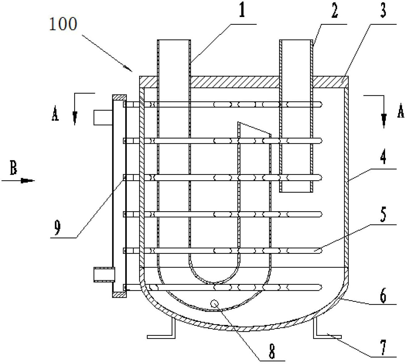
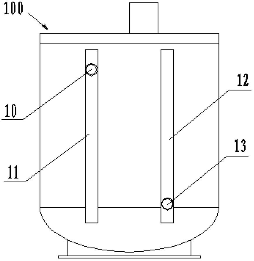
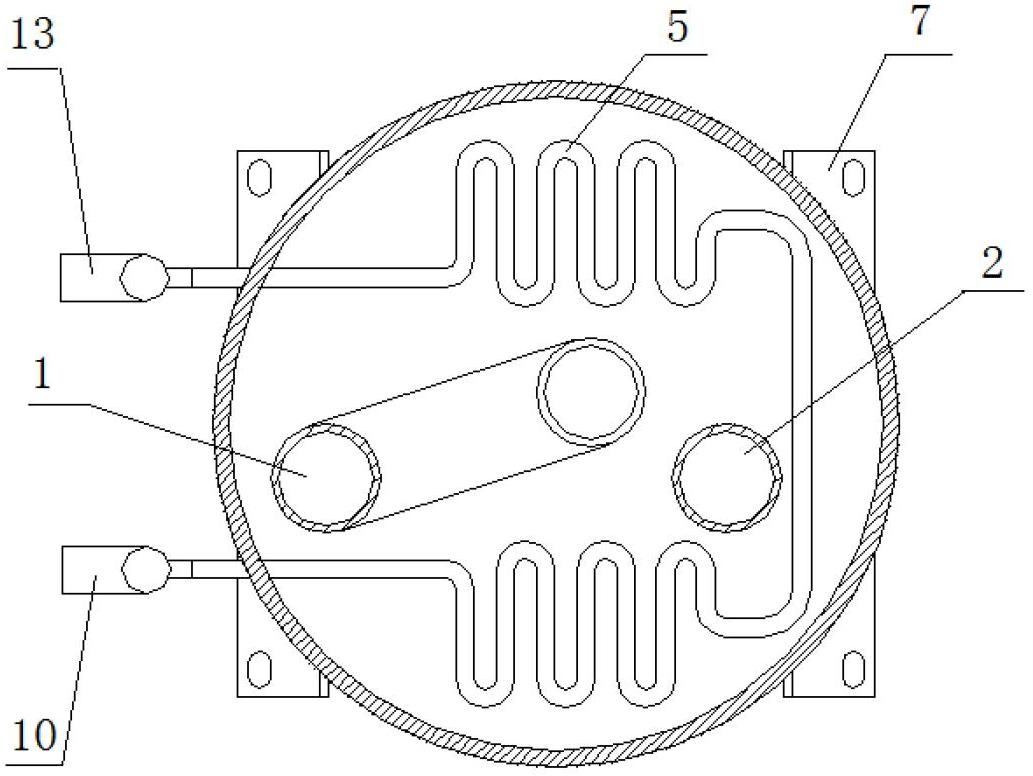
[0028] figure 1 , figure 2 and image 3 An embodiment of the gas-liquid separator with heat recovery function according to the present invention is shown. The gas-liquid separator 100 according to the present invention includes a superheating passage and a subcooling passage, and the superheating passage has an inlet pipe 2 for introducing refrigerant vapor into the gas-liquid separator 100 and an outlet pipe 1 for discharging refrigerant vapor out of the gas-liquid separator 100 The subcooling passage has one or more subcooling tubes 5 located in the gas-liquid separator 100 , and the refrigerant liquid flows through the subcooling tubes 5 and exchanges heat with the refrigerant vapor introduced into the gas-liquid separator 100 .

[0029] The subcooling passage also has a liquid uniform pipe 11, one end of the supercooled pipe 5 is connected to the liquid ...


PUM


Abstract

The invention discloses a gas-liquid separator with a heat-returning function and an application method thereof to an air conditioning unit. The gas-liquid separator with the heat-returning function comprises a superheating passageway and a supercooling passageway, and the superheating passageway is provided with an air inlet pipe used for bringing refrigerant vapour in the gas-liquid separator and an air outlet pipe used for exhausting the refrigerant vapour out of the gas-liquid separator; and the supercooling passageway is provided with one or more than one supercooling pipe arranged in the gas-liquid separator, refrigerant liquid flows through the supercooling pipe(s) so as to carry out heat exchange with the refrigerant vapour which is brought in the gas-liquid separator, thus realizing the superheating of the refrigerant vapour and supercooling of the refrigerant liquid. The gas-liquid separator and the application method provided by the invention can effectively promote the performance and efficiency of refrigerating / heating circulation and can be widely applied to the air conditioning unit.

Description

technical field [0001] The present invention relates to the field of air conditioning, more specifically, to a gas-liquid separator with a heat recovery function, which can be installed between an evaporator and a compressor to increase air Energy efficiency of heat and cold pump air conditioning units. The invention also relates to a method for applying the gas-liquid separator with heat recovery function in an air-conditioning unit. Background technique [0002] At present, air-conditioning units account for a relatively high proportion of my country's electricity load, so it is imminent to improve the energy efficiency of air-conditioning products. Air-cooled heat pump air-conditioning units are widely used because of their wide range of areas of use and easy installation and use. Insufficient heating capacity and low efficiency are an important issue that needs to be solved. [0003] In practice, measuring whether an air-conditioning product is energy-efficient is oft...

Claims


Application Information

Patent Timeline
IPC IPC(8): F25B43/00F25B40/00
Inventor 梁玉祥
Owner 四川同达博尔置业有限公司
Learn More