Multi-chamber, sequentially dispensing syringe

a syringe and multi-chamber technology, applied in the field of multi-chamber syringes, can solve the problems of insufficient syringes, increased risk of medication errors, and insufficient syringe selection,

Inactive Publication Date: 2010-09-07
THORNE CONSULTING & INTPROP
View PDF11 Cites 32 Cited by
  • Summary
  • Abstract
  • Description
  • Claims
  • Application Information

AI Technical Summary

Benefits of technology

[0048]It is a basic object to provide a discharge assembly which deters gas from being dispensed from the proximal chamber.

Problems solved by technology

It is currently estimated that nearly 90% of hospital patients receive IV medications, often through a variety of apparatus, including expensive electronic IV pumps and multi-channel infusion systems.
Noting that flushing usually necessitates use of a second flushing syringe (which is often currently factory pre-filled), the flushing syringe represents added cost, not only in clinician time, but in terms of required additional syringes.
Use of multiple syringes also increases risk of medication error (incorrect selection of flushing liquid) and introduction of microorganisms (a function of number of IV line or catheter accesses).
It is not good medical practice to dispense that gas into a patient line (e.g. an IV line).
It is Applicants' opinion that the filter disclosed in Howlett 910 and Thorne 720 can only be injection molded in relatively low cavitation molds, therefore limiting production efficiency and leading to increased cost.
Similarly, a requirement to slit a molded part requires at least one additional step after molding, again leading to increased cost.
For, when it is recognized that such a syringe may be desired to be used to dispense an accurately measured dose of a very expensive medication into an IV apparatus from a distal chamber of a multi-chamber syringe, dead space becomes an important issue.
Pfleger does not teach any means for purging the proximal chamber of gas or of retaining any gas in the proximal chamber while only dispensing liquid therefrom, making such a system unacceptable for delivering intravenous liquid medications to a patient.

Method used


Image

  • Multi-chamber, sequentially dispensing syringe
  • Multi-chamber, sequentially dispensing syringe
  • Multi-chamber, sequentially dispensing syringe

Examples


Embodiment Construction

[0085]Reference is now made to embodiments illustrated in FIGS. 1-29 wherein like numerals are used to designate like parts throughout. In this description, primes of numbers are used to represent parts which are similar, but not identical to other parts having the same numbers.

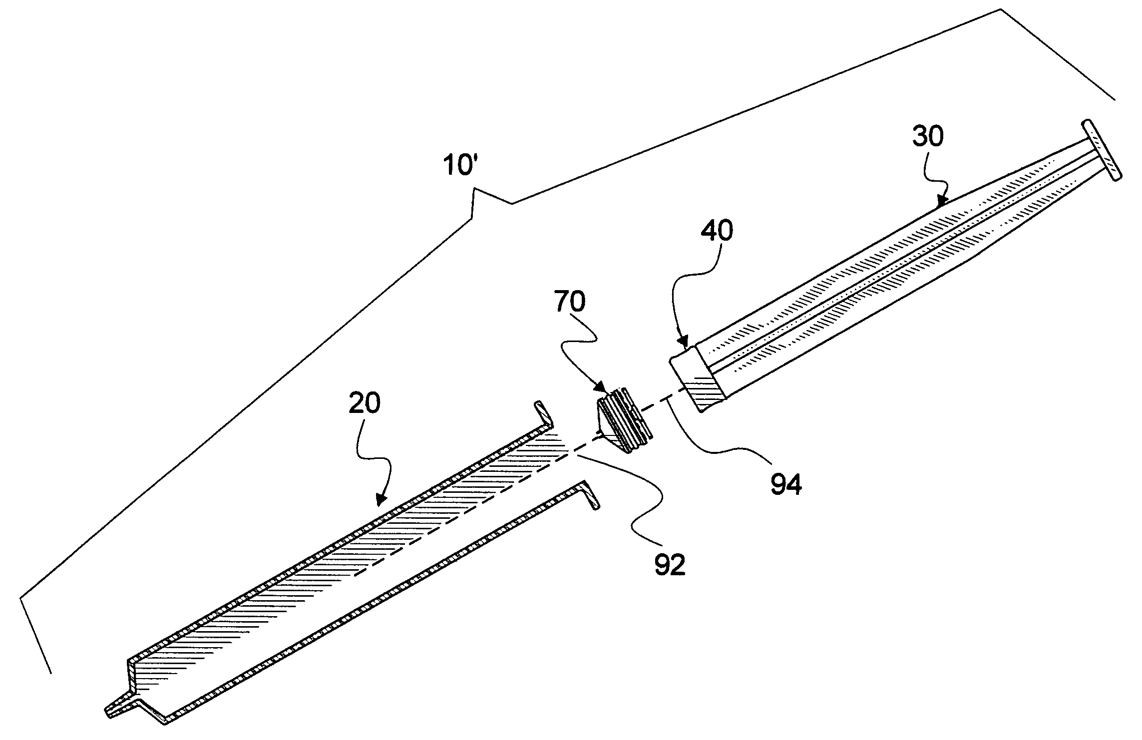
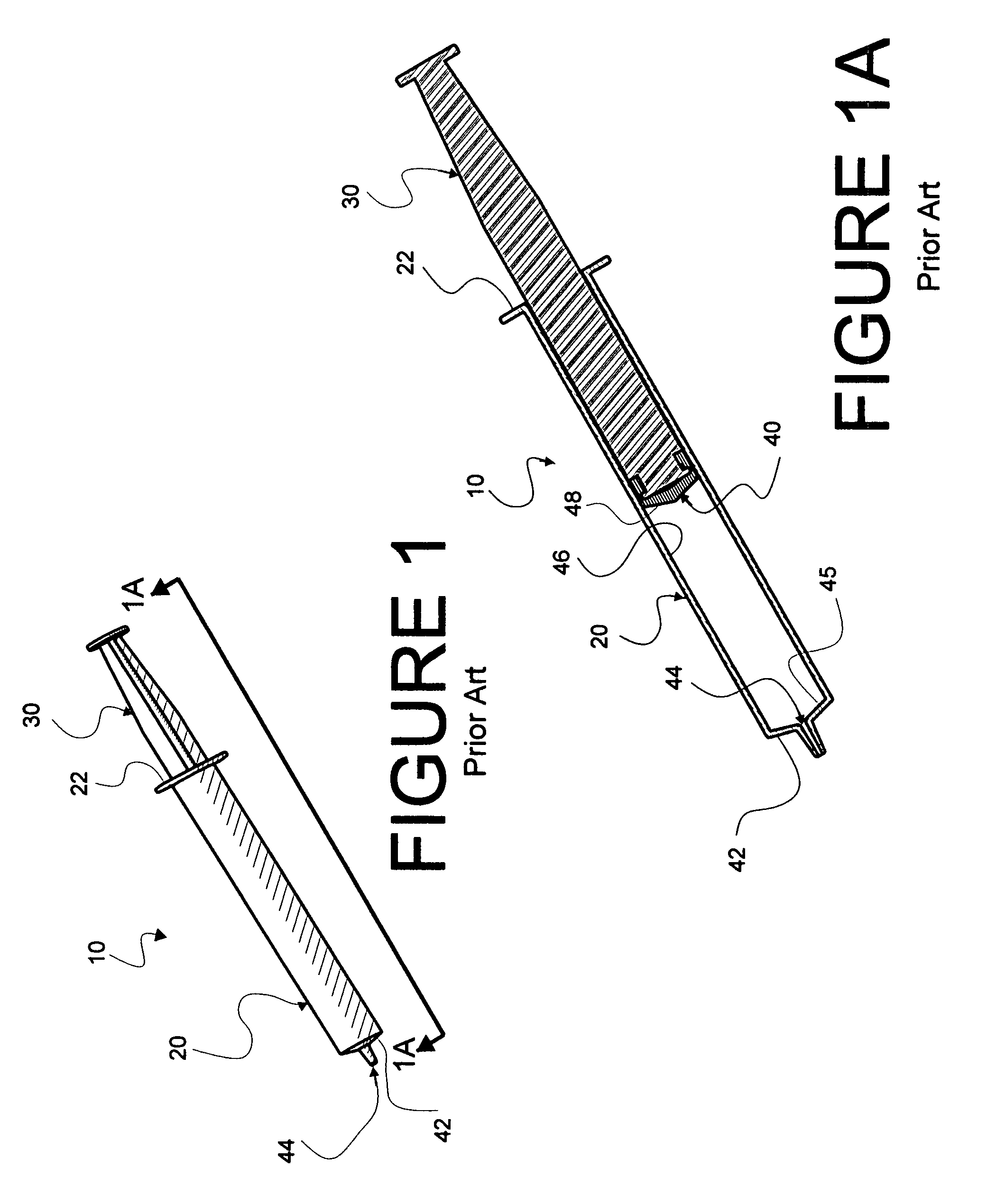
[0086]Prior art syringes (as exemplified by syringe 10) in FIGS. 1 and 1A, are available from a large number of commercial companies worldwide. Such syringes typically comprise an elongated hollow syringe barrel 20 which is open at a proximal end 22 to receive a syringe plunger rod 30 and associated plunger tip 40 and closed at a distal end 42 about a fluid transmission orifice 44 through a distal face 45. Generally, barrel 20 is of substantially constant diameter (within tolerances allowed by manufacturing methods, such as by injection molding for barrels made from synthetic resinous materials or modeled from glass). Plunger tip 40 is compressible and sufficiently elastic when compressed to provide an effici...


PUM


Abstract

A discharge assembly is disclosed which partitions a conventional syringe into proximal and distal chambers to provide a multi-chamber, sequentially dispensing syringe apparatus. Incorporated in the discharge assembly is a syringe stopper body and an associated valve stem which in combination form a valve. A syringe plunger communicates through fluid in the proximal chamber to force displacement of the discharge assembly. The valve is actuated by collision between a rigid member which is a part of the valve stem and the distal internal surface of the syringe. The discharge assembly may be made from two parts: (1) the stopper body (made from conventional syringe stopper material); (2) the valve (actuating) stem made from rigid material similar to material from which the syringe barrel is made. Key features of such a multi-chamber syringe apparatus are (1) fluids in the chambers are kept disparate; (2) the discharge assembly may be used in conventional syringes; (3) gas in a closed chamber, proximal to the discharge assembly, is retained in the proximal chamber while only liquid is dispensed therefrom.

Description

FIELD OF INVENTION[0001]This invention relates to multi-chamber syringes and, in particular, to multi-chamber syringes which employ conventional syringes and which dispense fluid sequentially from multiple chambers disposed within a single syringe barrel.DESCRIPTION OF RELATED ART[0002]Two recent U.S. patents disclose multi-chamber, sequential dose dispensing syringes from a conventional syringe barrel. A first is U.S. Pat. No. 6,997,910 B2, titled MULTI-CHAMBER, SEQUENTIAL DOSE DISPENSING SYRINGE was filed May 3, 2004 and issued Feb. 14, 2006 to Michael Wallace Howlett, et al. (Howlett 910). A second is U.S. Pat. No. 7,048,720 B1, titled MULTI-CHAMBER, SEQUENTIAL DOSE DISPENSING SYRINGE was filed Nov. 22, 2005 and issued May 23, 2006 to Gale H. Thorne, Jr., et al. (Thorne 720).[0003]Thorne 720 recites that, “During the last forty years, parenteral drug delivery has become increasingly common and sophisticated. It is currently estimated that nearly 90% of hospital patients receive I...

Claims


Application Information

Patent Timeline
Patent Type & Authority Patents(United States)
IPC IPC(8): A61M5/00A61M5/315
CPCA61M5/284A61M5/31596A61M5/288A61M2005/1787
Inventor THORNE, JR., GALE H.
Owner THORNE CONSULTING & INTPROP
Why Eureka
Try Eureka