MEMS closed chamber heat engine and electric generator

a closed-cell heat engine and electric generator technology, applied in steam engine plants, special engines, hot gas positive displacement engine plants, etc., can solve the problems of relatively complex engines, and achieve the effect of disabling the conductive transfer of thermal energy and enhancing heat transfer

Inactive Publication Date: 2005-12-27
NASA UNITED STATES OF AMERICA THE AS REPRESENTED BY THE ADMINISTATOR
View PDF18 Cites 32 Cited by
  • Summary
  • Abstract
  • Description
  • Claims
  • Application Information

AI Technical Summary

Problems solved by technology

Such engines are relatively complicated, requiring means for mixing fuel and air, and valve means for admitting fuel / air and for exhausting combustion byproducts.

Method used


Image

  • MEMS closed chamber heat engine and electric generator
  • MEMS closed chamber heat engine and electric generator
  • MEMS closed chamber heat engine and electric generator

Examples


Embodiment Construction

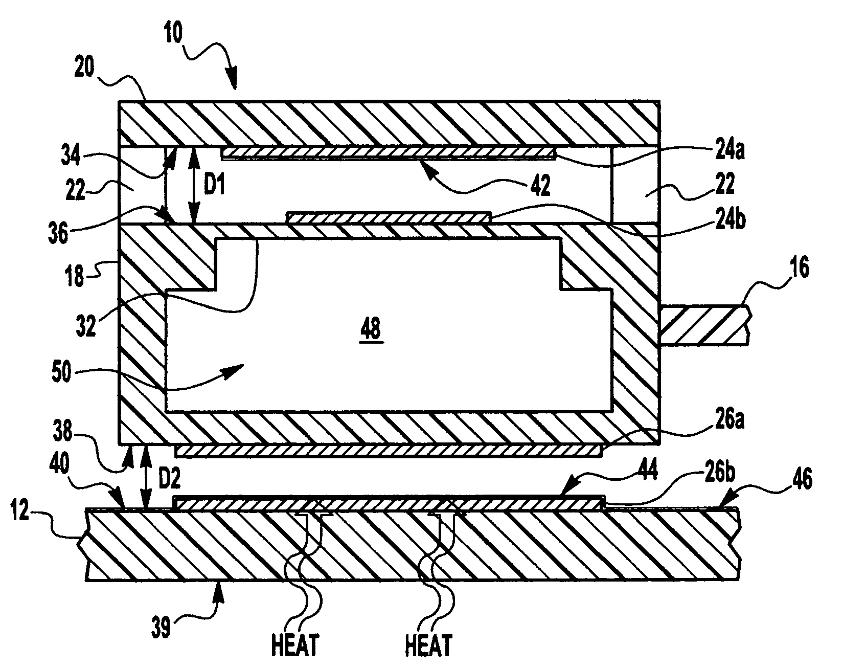
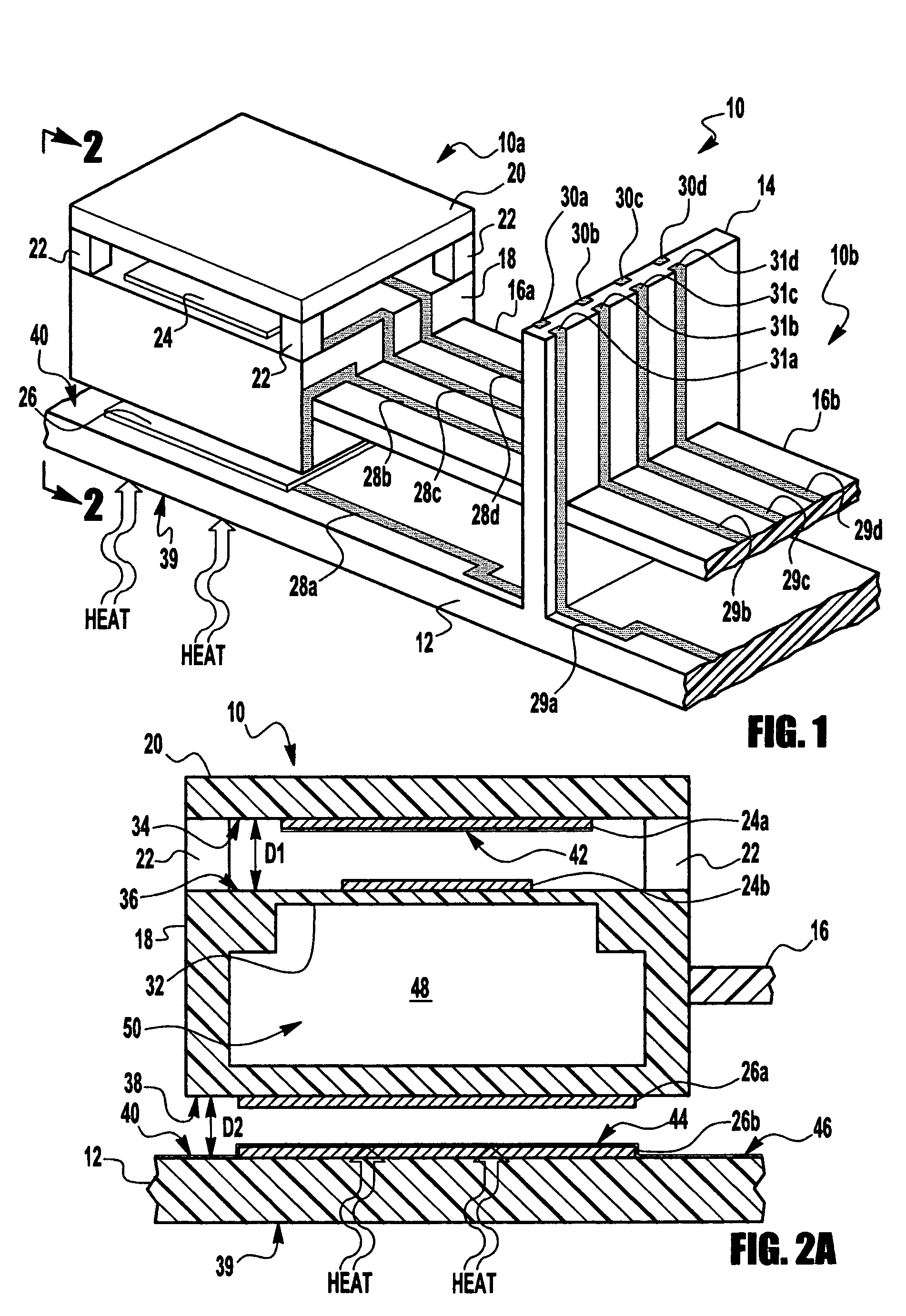
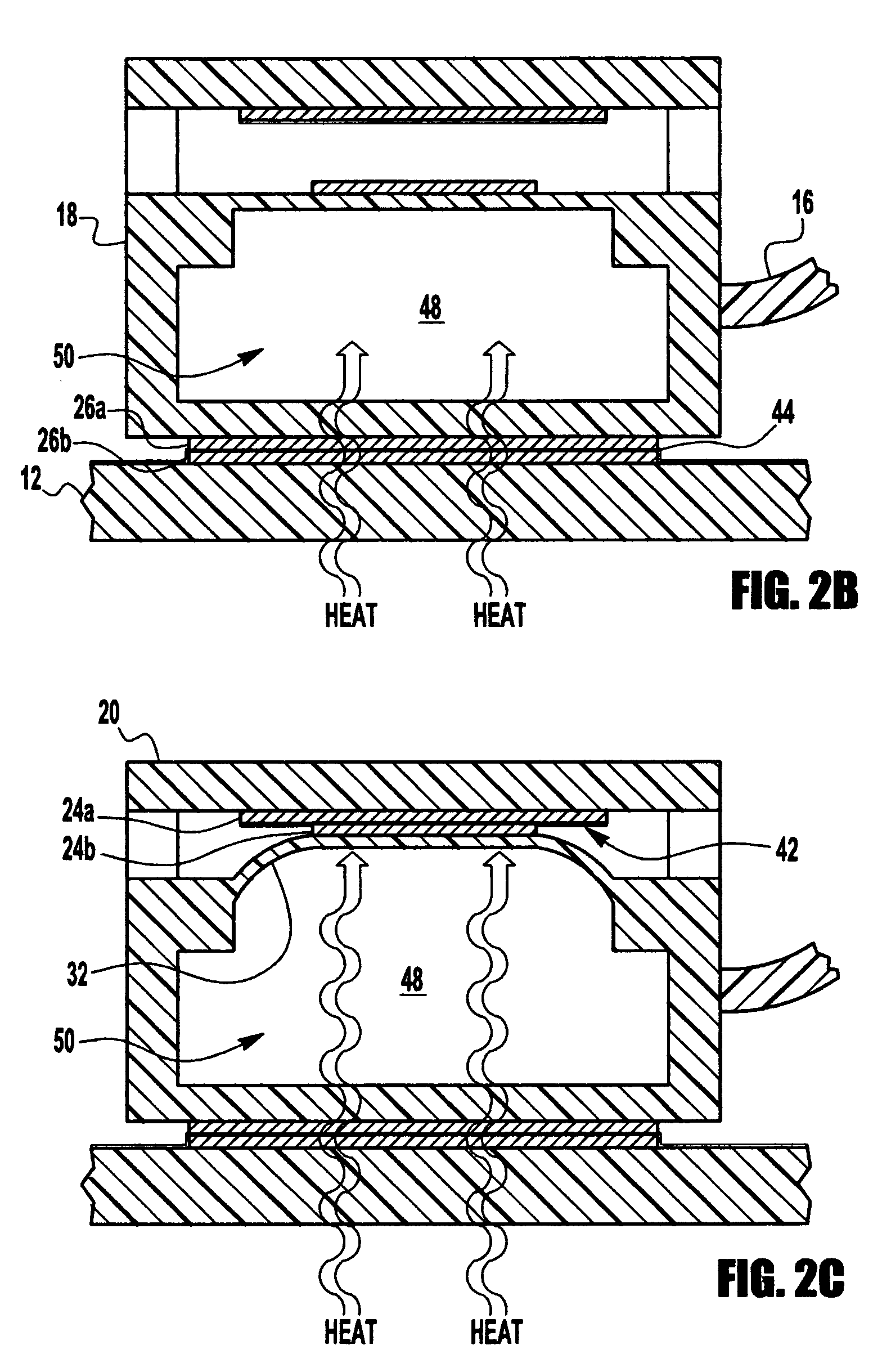
[0047]The present invention concerns a novel form of heat engine. In the preferred embodiments described herein, the heat engine is implemented using micro-electromechanical system (MEMS) technologies (also known as micromachining), and the heat engine is coupled with electrical generation means to form a MEMS heat engine and electric generator suitable for converting heat energy (e.g., waste heat) into electrical power. In a MEMS embodiment, the inventive heat engine (with or without electric generating means) is preferably implemented as a planar array of many miniaturized individual heat engines. For example, using common MEMS techniques and size scales, hundreds or even many thousands of individual heat engines could be formed on a single six-inch round silicon wafer.

[0048]FIG. 1 illustrates a first preferred embodiment of the invention. A heat engine / generator 10 comprises a planar array of one or more individual heat engine / generators 10a (shown complete) and 10b (shown only p...


PUM


Abstract

A heat engine, preferably combined with an electric generator, and advantageously implemented using micro-electromechanical system (MEMS) technologies as an array of one or more individual heat engine / generators. The heat engine is based on a closed chamber containing a motive medium, preferably a gas; means for alternately enabling and disabling transfer of thermal energy from a heat source to the motive medium; and at least one movable side of the chamber that moves in response to thermally-induced expansion and contraction of the motive medium, thereby converting thermal energy to oscillating movement. The electrical generator is combined with the heat engine to utilize movement of the movable side to convert mechanical work to electrical energy, preferably using electrostatic interaction in a generator capacitor. Preferably at least one heat transfer side of the chamber is placed alternately into and out of contact with the heat source by a motion capacitor, thereby alternately enabling and disabling conductive transfer of heat to the motive medium.

Description

[0001]The invention described herein was made by an employee of the United States Government and may be manufactured and used by or for the Government for Government purposes without the payment of any royalties thereon or therefore.TECHNICAL FIELD OF THE INVENTION[0002]The present invention relates to heat engines utilizing a motive medium expanding / contracting in a closed chamber and to said heat engines in combination with electrical generating means, and, more particularly to said engines and generators implemented with micro-electromechanical system (MEMS) technologies.BACKGROUND OF THE INVENTION[0003]Conversion of heat energy into electrical energy (i.e., a heat engine / generator) is highly desirable for space missions, for example, to convert the heat of radioisotope decay into power for the instruments of spacecraft. It is also desirable for commercial uses, particularly if the conversion devices are small and low cost, and even more so if they can be enabled to work on waste...

Claims


Application Information

Patent Timeline
Patent Type & Authority Patents(United States)
IPC IPC(8): F01B29/00F02G1/04F03G7/06
CPCB82Y15/00F02G1/04F03G7/06F02G2250/31F05B2250/82F05B2250/84
Inventor LANDIS, GEOFFREY A.
Owner NASA UNITED STATES OF AMERICA THE AS REPRESENTED BY THE ADMINISTATOR
Why Eureka
Try Eureka