
Control system for internal combustion engine with catalyst for purifying exhaust gas

a technology of control system and internal combustion engine, which is applied in the direction of electric control, ignition automatic control, machines/engines, etc., can solve the problems that the combination of control of combustion and each other has not yet been built up in success

Inactive Publication Date: 2004-03-25
HITACHI LTD
View PDF0 Cites 34 Cited by
  • Summary
  • Abstract
  • Description
  • Claims
  • Application Information

AI Technical Summary

Problems solved by technology

Neither such a control technology that the warm-up of an engine and the warm-up of catalyst for purification of exhaust gas are associated with each other so as to carry out rational control, nor such a technology of short-time warm-up of an internal combustion engine that the control of a cooling water system and the control of combustion are combined with each other has not yet been built up in success.

Method used


Image

  • Control system for internal combustion engine with catalyst for purifying exhaust gas
  • Control system for internal combustion engine with catalyst for purifying exhaust gas
  • Control system for internal combustion engine with catalyst for purifying exhaust gas

Examples


second embodiment

[0079] Referring to FIGS. 14 to 16, explanation will be hereinbelow made of the present invention.

[0080] Referring to FIG. 14 which shows the configuration of an engine in the second embodiment, this configuration is the same as that shown in FIG. 9, except that there are provided a turbocharger 15 for supercharging the intake air in an exhaust pipe 11, a cooling passage 6a for cooling the turbocharger 15, a bypass passage 6b bypassing the cooling passage 6a, and a bypass valve 16 for blocking the flow in the bypass flow passage 6a.

[0081] The cooling passage 6a and the bypass passage 6b are alternately connected to the engine cooling passage 6 through switching control of the bypass valve 16.

[0082] Referring to FIG. 15 which is a control flow-chart of the bypass valve 16 in this embodiment, at step 1501, a value from the catalyst temperature sensor 13 is read, and at step 1502, whether the temperature of the catalyst is greater than an activation temperature thereof or not is determ...


PUM


Abstract

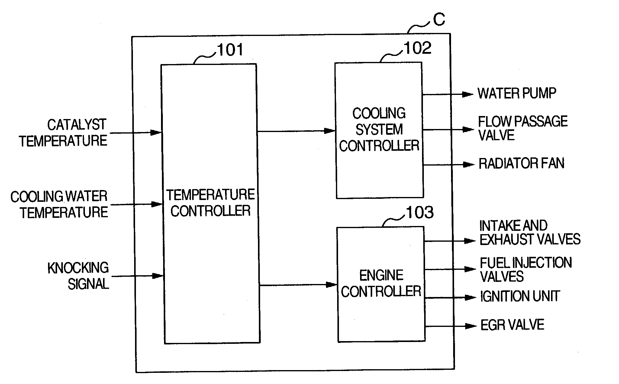
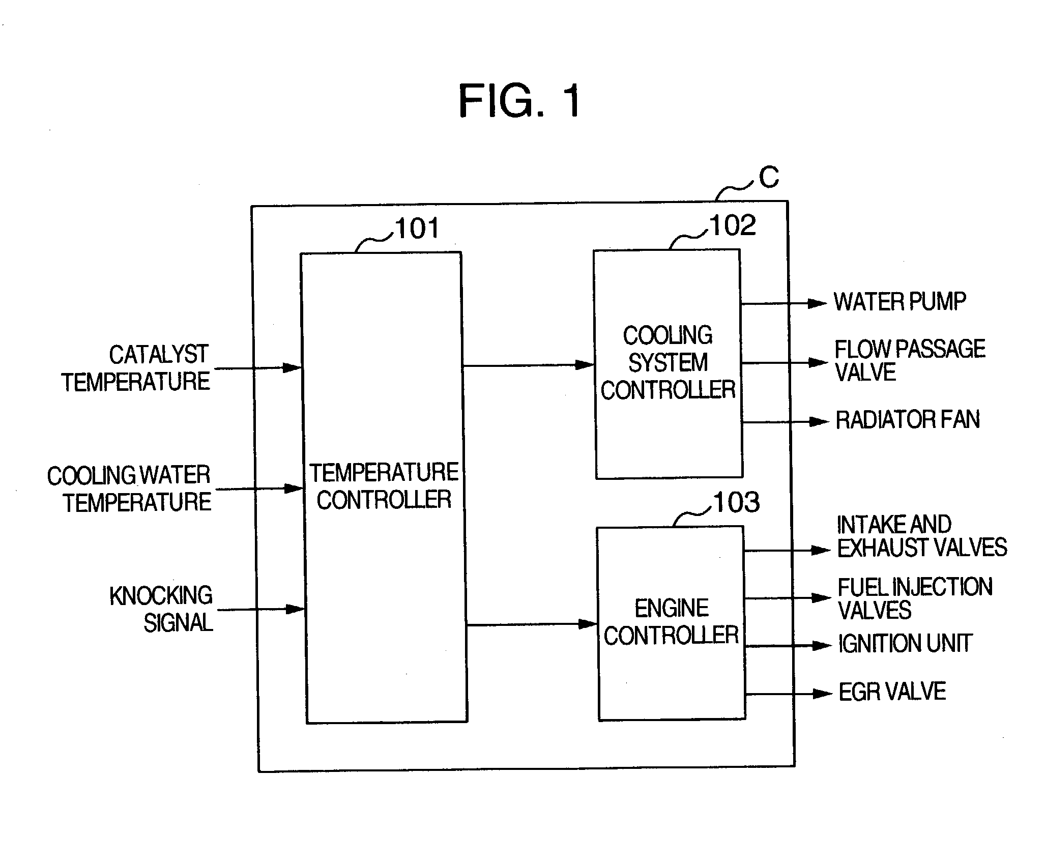
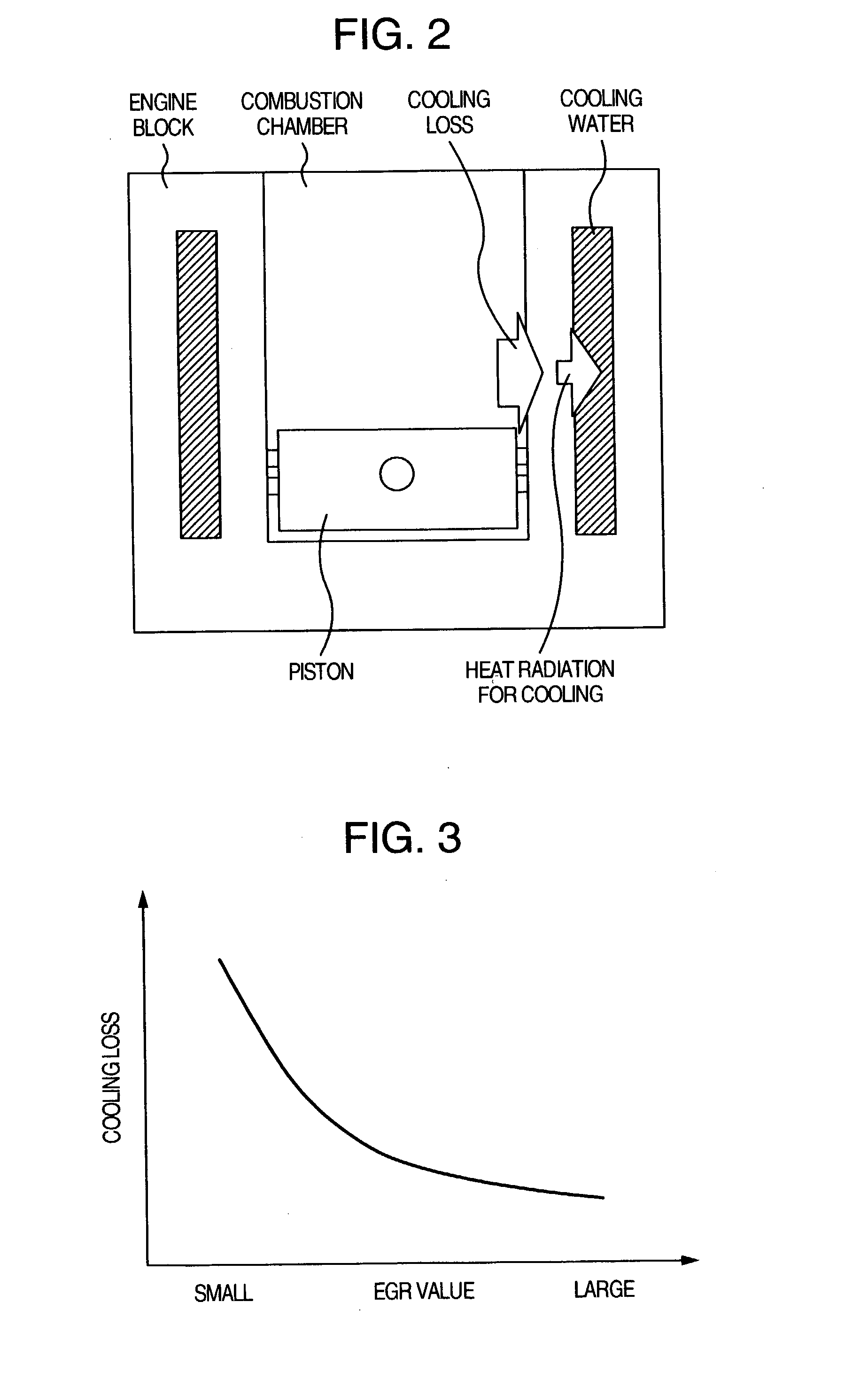
There is provided a control system for an internal combustion engine, which aim for early warm-up of catalyst and the engine in order to control a cooling loss and a heat radiation for cooling in such a way that the warm-up of the catalyst is carried out prior to the warm-up of the engine. That is, if the temperature of the catalyst is not greater than an activation temperature, there is carried out at least one of (1) retardation control of the ignition timing, (2) stopping control of a water pump for engine cooling water, (3) lowering control of the flow rate of the cooling water, but if the temperature of the catalyst is higher than the activation temperature, there is carried out at least one of control of the water pump in accordance with a temperature of the cooling water and control of retardation of the ignition timing, until the temperature of the cooling water reaches a warm-up temperature which is a normal operation temperature of the engine.

Description

[0001] The present invention relates to a control system for an internal combustion engine, which incorporates catalyst for purifying exhaust gas, and in particular to a technology of fast activation of catalyst for purification of exhaust gas from an internal combustion engine, by controlling an engine cooling system or the like.RELATED ART[0002] As disclosed in, for example, JP-A-2000-34584 or JP-A-2000-45843, there have been well-known many technologies of inhibiting radiation of heat from an engine to cooling water during a cold start in order to shorten the time of warm-up of the engine.[0003] For example, the JP-A-2000-34584 discloses such a technology that the supply of cooling water is controlled in accordance with a temperature of a combustion chamber during operation of an engine so as to promote warm-up of the engine while the temperature of the wall surface of a combustion chamber, which correlates to a quantity of emergence of unburned HC components during a cold start ...

Claims


Application Information

Patent Timeline
IPC IPC(8): F01N3/20F01P3/12F01P7/04F01P7/16F02B1/12F02D41/02F02D43/00F02P5/15F02P5/152F02P5/153
CPCF01P7/164F01P2025/44F01P2025/46F02B1/12Y02T10/26F02P5/1506F02P5/152Y02T10/46F02D41/0255Y02T10/12Y02T10/40
Inventor IIHOSHI, YOICHIMIYAZAKI, TAIZO
Owner HITACHI LTD
Learn More