Multi-mode scanning imaging system

a scanning imaging and multi-mode technology, applied in the field of scanning imaging systems, can solve the problems of non-ideal spacing between the objectives in different rows, and the tolerances of manufacturing, and achieve the effect of avoiding the formation of overlapping rows of objectives

Inactive Publication Date: 2004-03-25
DMETRIX INC
View PDF7 Cites 47 Cited by
  • Summary
  • Abstract
  • Description
  • Claims
  • Application Information

AI Technical Summary

Problems solved by technology

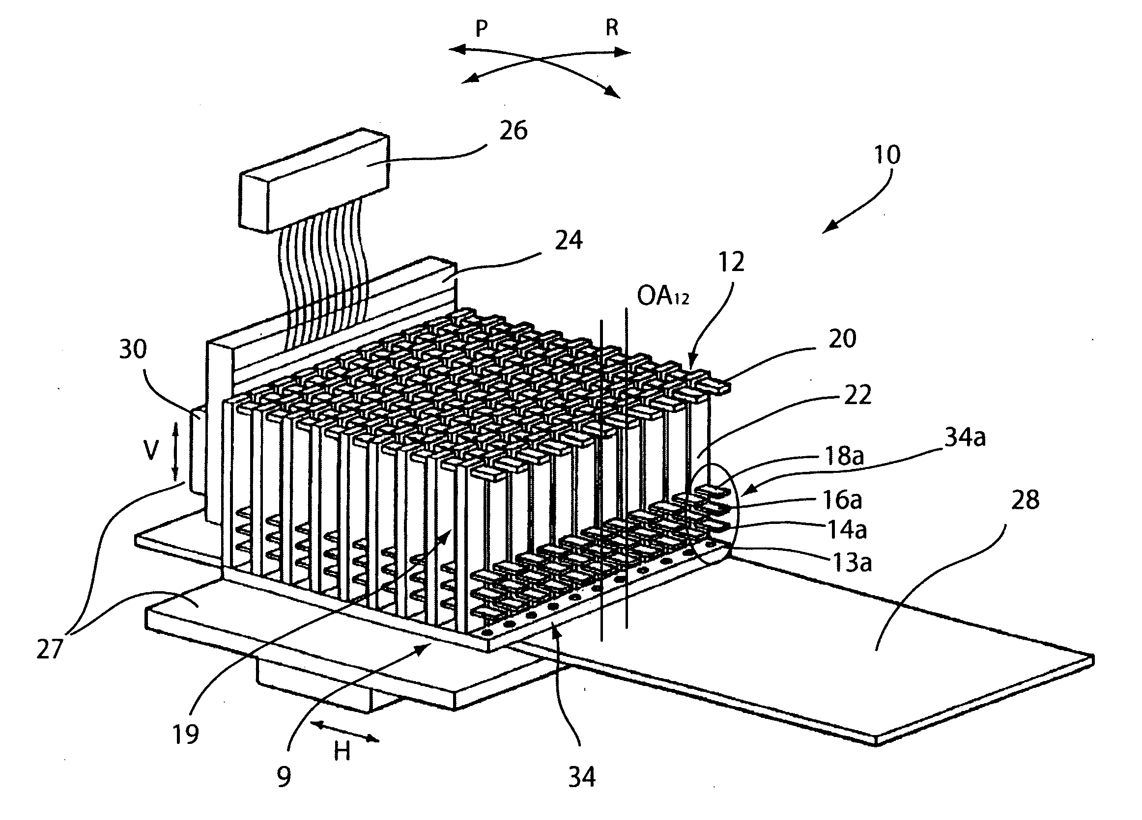
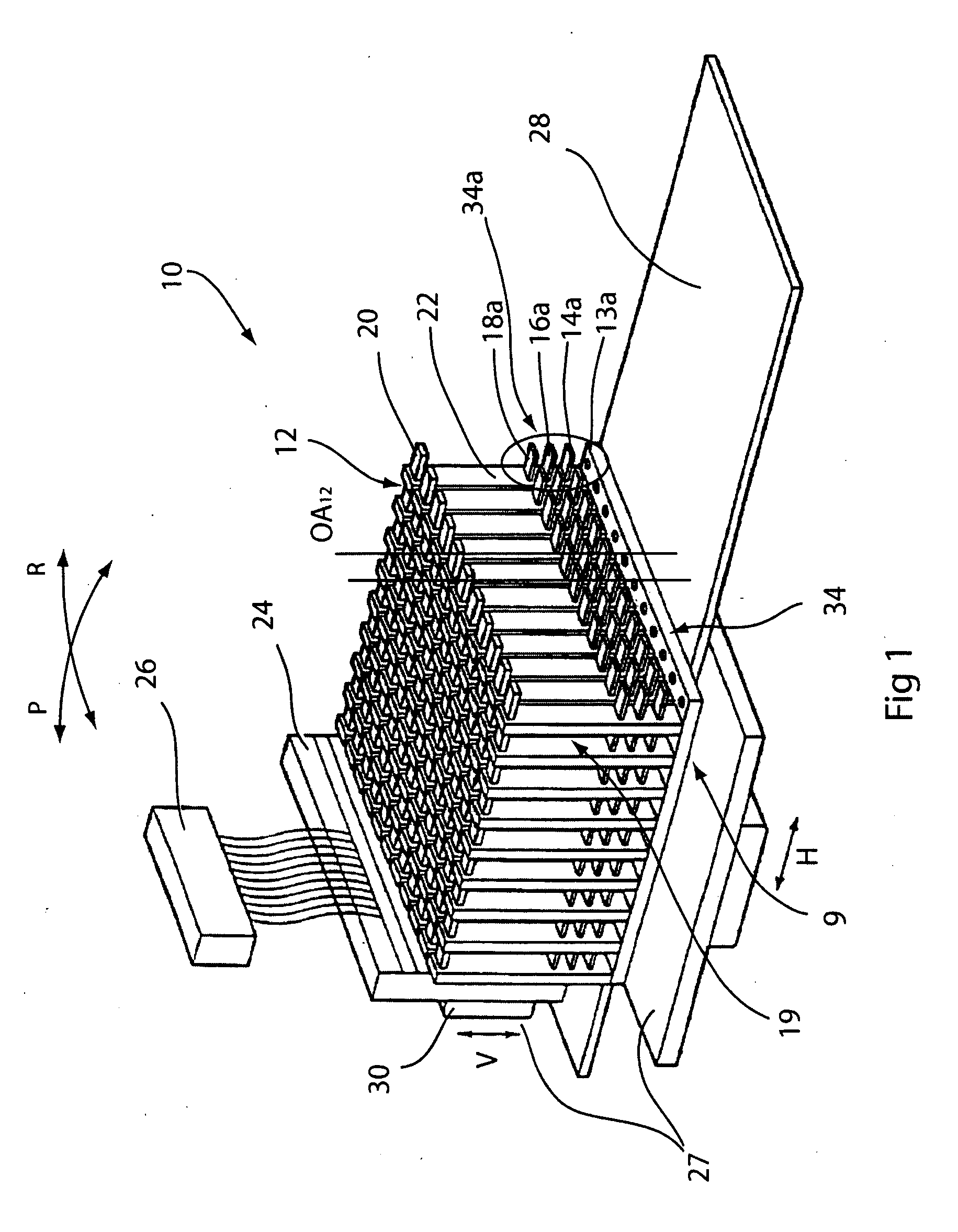
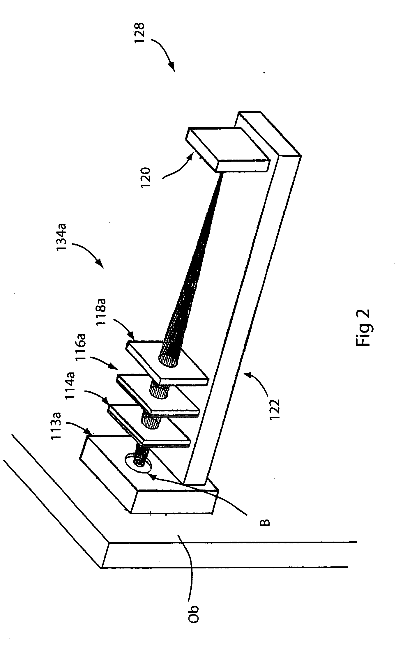
Manufacturing tolerances also produce non-ideal spacing between the objectives in different rows, in the longitudinal or scan direction.

Method used


Image

  • Multi-mode scanning imaging system
  • Multi-mode scanning imaging system
  • Multi-mode scanning imaging system

Examples


embodiment 100

[0077] Turning to FIGS. 13A and 13B, an exemplary first preferred embodiment 100 of a multi-mode scanning imaging system according to the present invention is shown. Three array microscopes 110, specifically 110a, 110b, and 110c, are positioned side-by-side with respect to an object to be imaged, which for exemplary purposes may be a microscope slide 128. Each of the three microscopes 110 is positioned to image a different portion of the object 128 at the same time. As the object is scanned by all three microscopes, such as by moving the object relative to the three microscopes in the scan direction "S," the scanning time required to scan the entire object is reduced by approximately a factor of three.

[0078] FIGS. 14A and 14B show an exemplary second embodiment 200 of a multi-mode scanning imaging system according to the present invention. Three array microscopes 210, specifically 210a, 210b, and 210c, are positioned side-by-side with respect to an object 228 to be imaged. Each of t...

embodiment 600

[0110] The method of combination depends on the modes of operation of the imaging system. For example, where as in the embodiments 200 and 500 a plurality of microscope arrays are used in a mode of operation that scans different portions of the same object, the data are concatenated to join the data contiguously. On the other hand, where as in the embodiment 600 the arrays are used in a mode of operation wherein each array scans a different object, the data are not necessarily combined but may be concatenated if desired.

[0111] The embodiment 200 provides an example of a mode of operation in which image data are correlated. Particularly, the different R, G, and B images are overlaid to produce a composite color image. In the embodiment 300, the image data are also overlaid in such manner as to produce a 3-D composite image. In the embodiment 400, image data from the microscope 410a is correlated to combine R, G and B images, and the composite image is further correlated with the fluo...


PUM


Abstract

A multi-mode scanning imaging system. The system includes a plurality of sets of optical elements and a scanning mechanism. Each set is disposed with respect to a corresponding image plane and configured to image respective portions of an object. A scanning mechanism produces relative translation between the sets and the object so as to scan the object. Sets of image sensors corresponding to the sets of optical elements are adapted to capture image data representative of the respective portions of the object. A mode implementation system coordinates the image data according to one or more desired modes of operation of the imaging system.

Description

[0001] This application claims the benefit of the applicants' provisional application Serial No. 60 / 413,399, incorporated by reference herein in its entirety.FIELD OF THE INVENTION This invention relates to a scanning imaging system providing for multiple modalities of operation.[0002] To obtain an image of an object, it is often necessary to scan the object by moving one of the object and the imaging system relative to the other. One common use in which this need arises is light microscopy, particularly where a tissue specimen is being imaged for diagnostic analysis; however, image scanning may be employed where there is no magnification, or where there is demagnification.[0003] In microscopy, the need arises particularly when using conventional, single-axis, microscopes, where resolution must be traded off with the microscope's field of view ("FOV") i.e., the FOV must be decreased in order to increase resolution. Therefore, a microscope with an objective having a FOV that is too s...

Claims


Application Information

Patent Timeline
Patent Type & Authority Applications(United States)
IPC IPC(8): G02B21/00G02B21/36
CPCG02B21/367G02B21/002
Inventor OLSZAK, ARTUR G.LIANG, CHENDESCOUR, MICHAEL R.
Owner DMETRIX INC
Why Eureka
Try Eureka