Dynamic impedance comparator

a comparator and dynamic technology, applied in the field of dynamic impedance comparator, can solve the problems of inability to check reactive impedances, use visual feed back, and relatively high cost, and the current method is not primarily geared for comparison

Inactive Publication Date: 2004-03-25
LAWRENCE CLIFTON
View PDF6 Cites 1 Cited by
  • Summary
  • Abstract
  • Description
  • Claims
  • Application Information

AI Technical Summary

Problems solved by technology

The Test Equipment most commonly used to verify component properties is the multi-meter, and since most multi-meters operate with a D.C. test Signal, they are unable to check Reactive Impedan

Method used


Image

  • Dynamic impedance comparator
  • Dynamic impedance comparator
  • Dynamic impedance comparator

Examples


Embodiment Construction

[0008] The Operation of the Device To Audibly Express Impedance Measurement is explained using the following thirteen (13) diagrams.

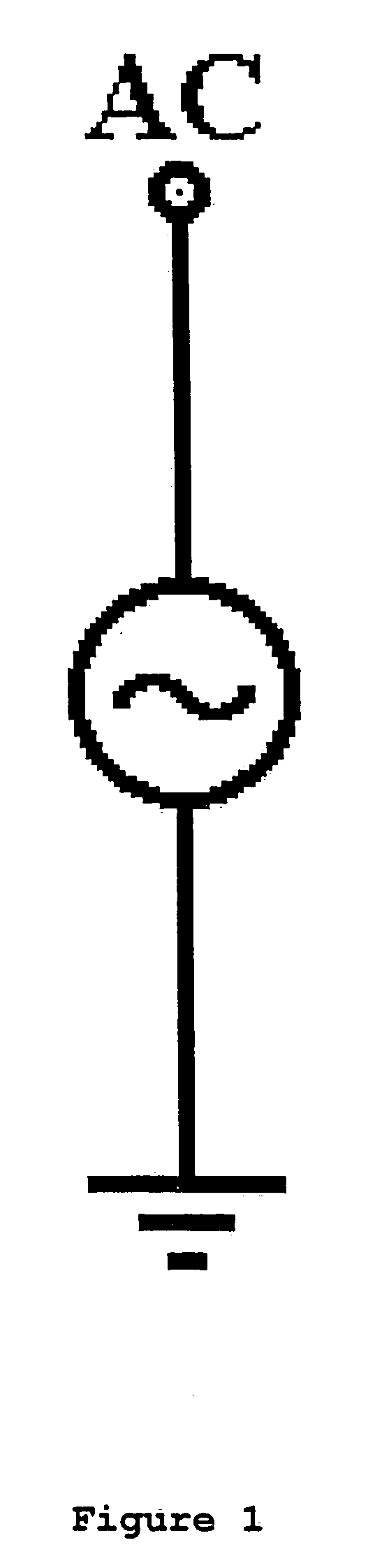
[0009] FIG. 1. An Audio Frequency Voltage Generator called `AC`, whose Output is applied to the points labeled `In`, in Figure two (2) through Figure six (6).

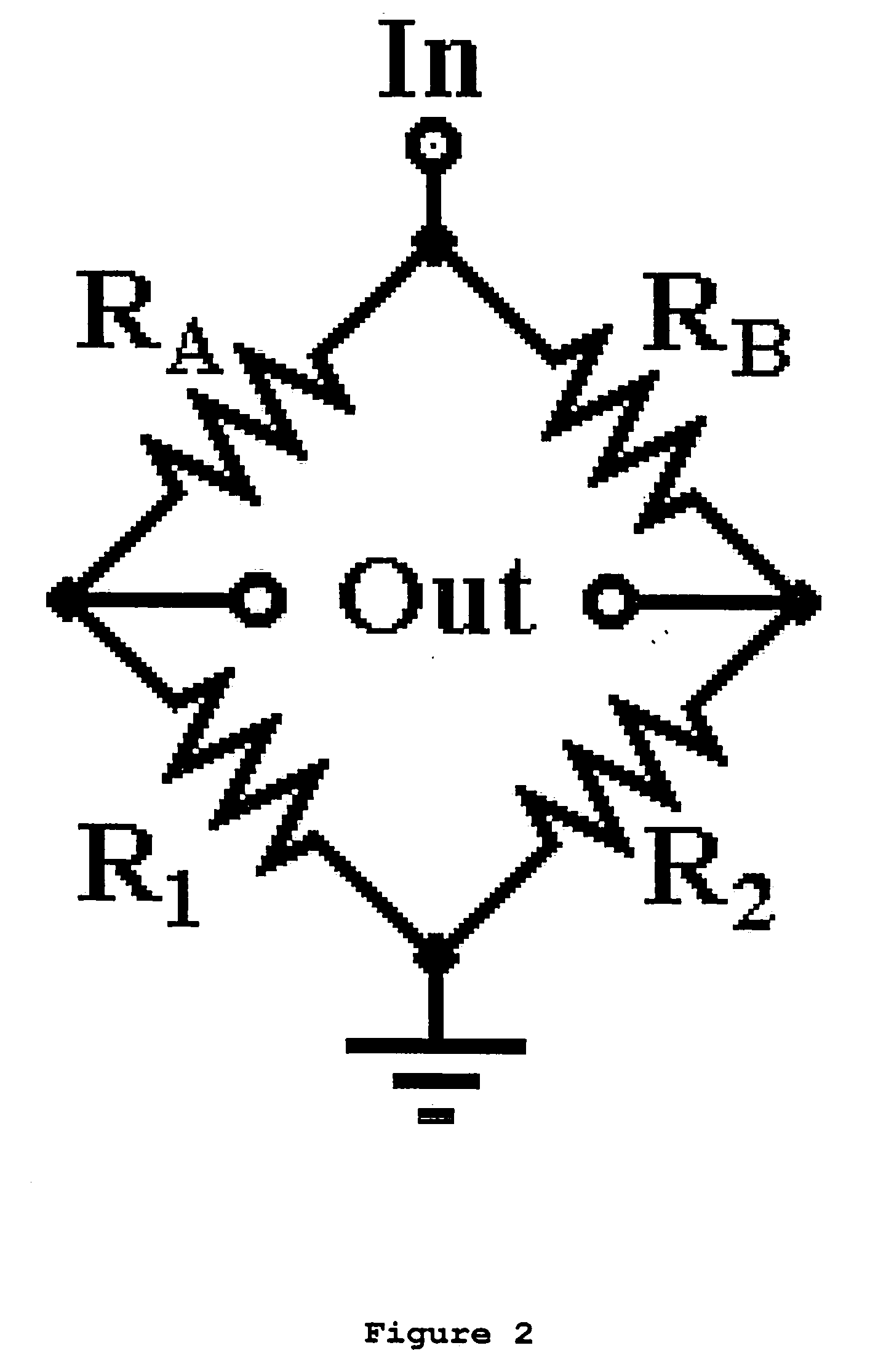
[0010] FIG. 2. (The Fundamental Circuit). A Resistive Bridge where `R1` equals `R2`, and `RA` and `RB` are of unknown value. `R1` and `R2` also act as current limiters in the Circuit. Any difference in the Resistances of `RA` and `RB`, causes a Voltage to be present across the points labeled `Out`. The Circuit can be said to consist of two halves. One consisting of `RA` and `R1`, and the other consisting of `RB` and `R2`.

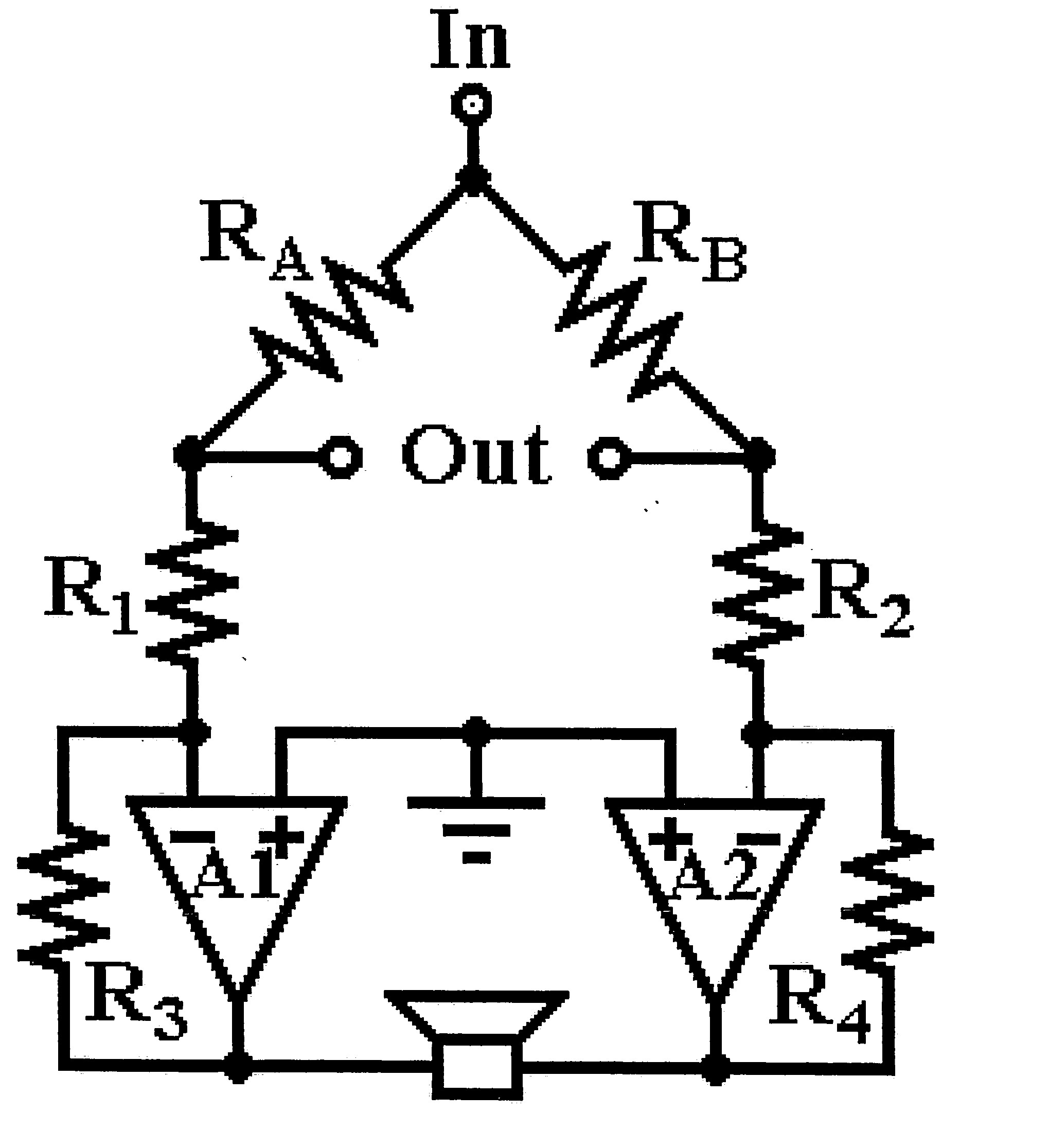
[0011] NB. If any Measuring Device were to be connected across the terminals labeled `Out`, the power drawn by this Device, would change the Voltage across these terminals, hence the following configuration.

[0012] FIG. 3. Operational Anplifiers (Op-Amps) `A1` and `A2`, and Resistor...


PUM


Abstract

An Audio Feedback Impedance Comparison Device to audibly express Impedance differences between/amongst components, circuits, materials, substances etc., to make use of the aural sense, while relieving eye, neck and mental strain, as well as reduce probe time. This is achieved by allowing simultaneous yet focused attention to be paid to all aspects of an impedance probe, i.e. hand-eye coordination of probe positioning, while aurally monitoring the feedback, instead of the common practices/methods where eyes have to be re-focused on visual feedback devices. The use of an alternating signal allows "through" comparison, where multiple components some of which are impervious to static signal, contribute to overall impedance. The device can be used to inject and/or detect/trace the presence of an audio signal in an active circuit. With the aid of transducers, this Device may be used with other forms of energy.

Description

[0001] This Invention is as a result of a quest to find a cheap, simple and effective way to troubleshoot malfunctions due to Impedance change, since component failure is usually reflected as such.DESCRIPTION OF PRIOR ART[0002] In Electronics, the current method of troubleshooting is generally to verify that individual components within a circuit retain their rated manufactured properties. The various properties usually require different methods and sometimes full or partial removal / isolation, to obtain accurate measurements. The Test Equipment most commonly used to verify component properties is the multi-meter, and since most multi-meters operate with a D.C. test Signal, they are unable to check Reactive Impedances. The main feedback from Multi-meters is visual, therefore using a Multi-meter requires firstly, visual attention in the positioning of the probes, then, refocusing on a display to read a value. Comparison between two circuits requires either two multi-meters, or checkin...

Claims


Application Information

Patent Timeline
IPC IPC(8): G01D7/12G01RG01R27/16H01P5/08H03H7/38H04R29/00
CPCG01D7/12G01R27/00
Inventor LAWRENCE, CLIFTON
Owner LAWRENCE CLIFTON
Why Eureka
Try Eureka