Method for determining, recording and sending GPS location data in an underwater environment

Inactive Publication Date: 2004-04-08
VIAVI SOLUTIONS INC
View PDF5 Cites 75 Cited by
  • Summary
  • Abstract
  • Description
  • Claims
  • Application Information

AI Technical Summary

Problems solved by technology

Unfortunately, GPS is not effective underwater due to the inability of GPS signals to properly propagate in water.
Naturally, in this configuration, accuracy is restricted to the inherent tolerances of the GPS receiver combined with error introduced by the actual vertical proximity (and related horizontal offset from the GPS receiver) of the diver or vehicle which is obviously influenced by prevailing currents and the length of the tether.
Although GPS can be deployed on the water in a rather cumbersome configuration, such as described above, current conventional thought in this area states that GPS is not practical to use underwater.
However, for some purposes such as underwater salvage or archaeology in the hostile environment of the ocean or other bodies of water, especially when subject to changes of visibility conditions, accurate position location can be e

Method used


Image

  • Method for determining, recording and sending GPS location data in an underwater environment
  • Method for determining, recording and sending GPS location data in an underwater environment
  • Method for determining, recording and sending GPS location data in an underwater environment

Examples


first embodiment

[0020] First Embodiment

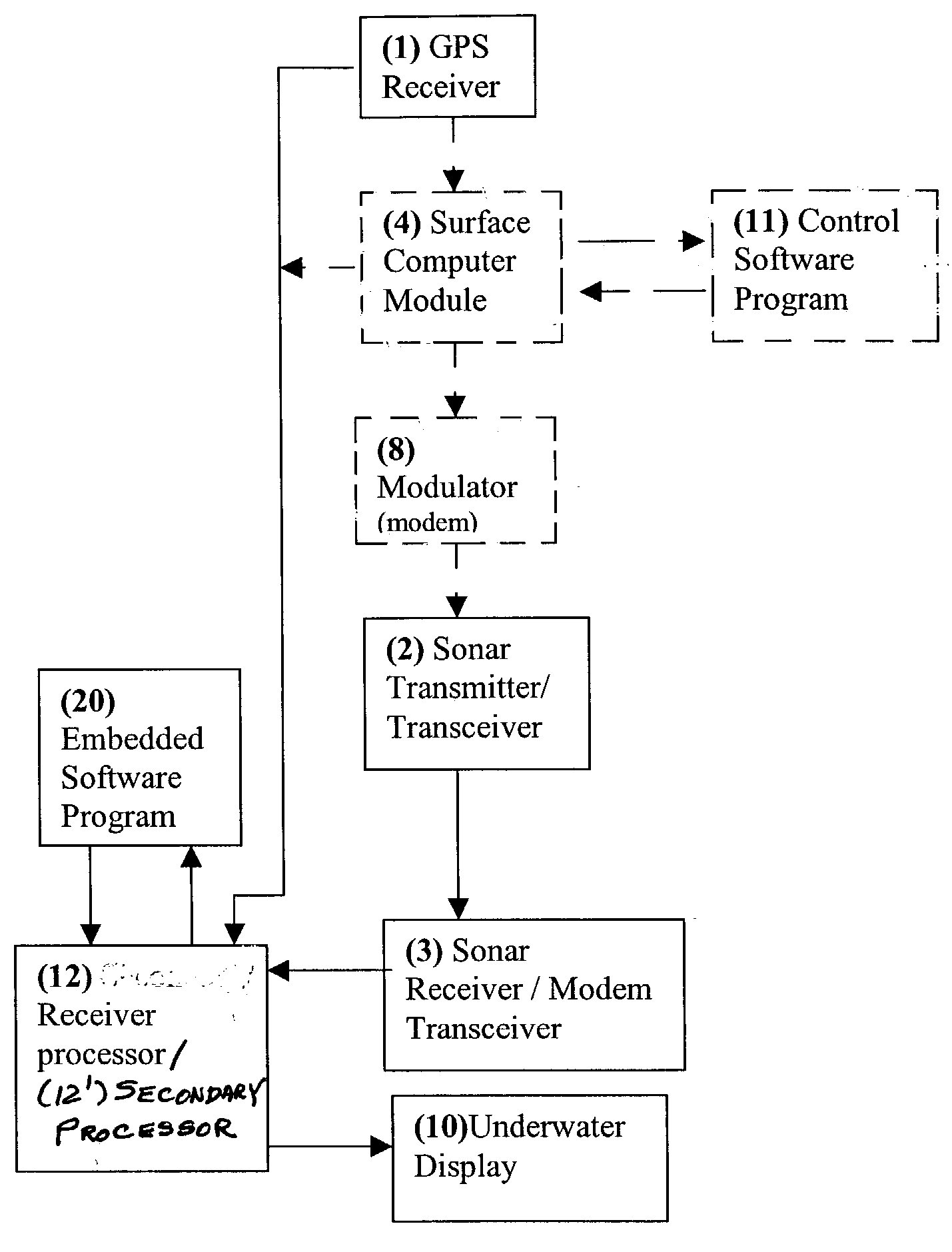
[0021] Referring now to FIG. 2, a first embodiment of the invention will be discussed to convey an understanding of the basic principles of the invention sufficient to its successful practice. In the simplest form of this embodiment, a GPS receiver 1 is mounted on a boat preferably as discussed above in connection with FIG. 1. A small computer (e.g. surface computer module 4 and control software program 11) may be connected to the GPS receiver but is not necessary in the simplest form of the invention. A modulator 8 may be connected to the computer. A sonar transmitter 2 is provided and may be connected to the modulator 8. A diver or vehicle is in the water and preferably attached to a sonar receiver 3 associated with a receiver processor 12 and an embedded software program 20 which provides ranging data as in the EyeSee.TM. system described above and the combining of the ranging data with the GPS data input to processor 12 form GPS receiver 3 or otherwise as ...

embodiment three

[0031] Embodiment Three

[0032] In this more complex embodiment illustrated in FIG. 4, the basic hardware configuration described in Embodiment One (FIG. 2) and / or Embodiment Two (FIG. 3) is augmented for increased functionality. The sonar transmitter 2 connected to the support vessel is pre-selected to broadcast of a first channel such as at Frequency A and is thus designated 2A. The sonar receiver 3, attached to the diver or vehicle is preselected and filtered to receive only Frequency A transmissions (also used as the sonar communication link for ranging) and thus designated 3A. A demodulator 18 is connected to the sonar receiver (for its input) and the secondary processor 12' (for its output) and preferably residing on the sonar receiver 3A attached to the diver or vehicle.

[0033] A modulator 8B is connected to the secondary processor 12' which is attached to the diver or vehicle. A sonar transmitter 2B preselected to broadcast on a second channel such as at Frequency B is connecte...

embodiment

[0040] Embodiment Four

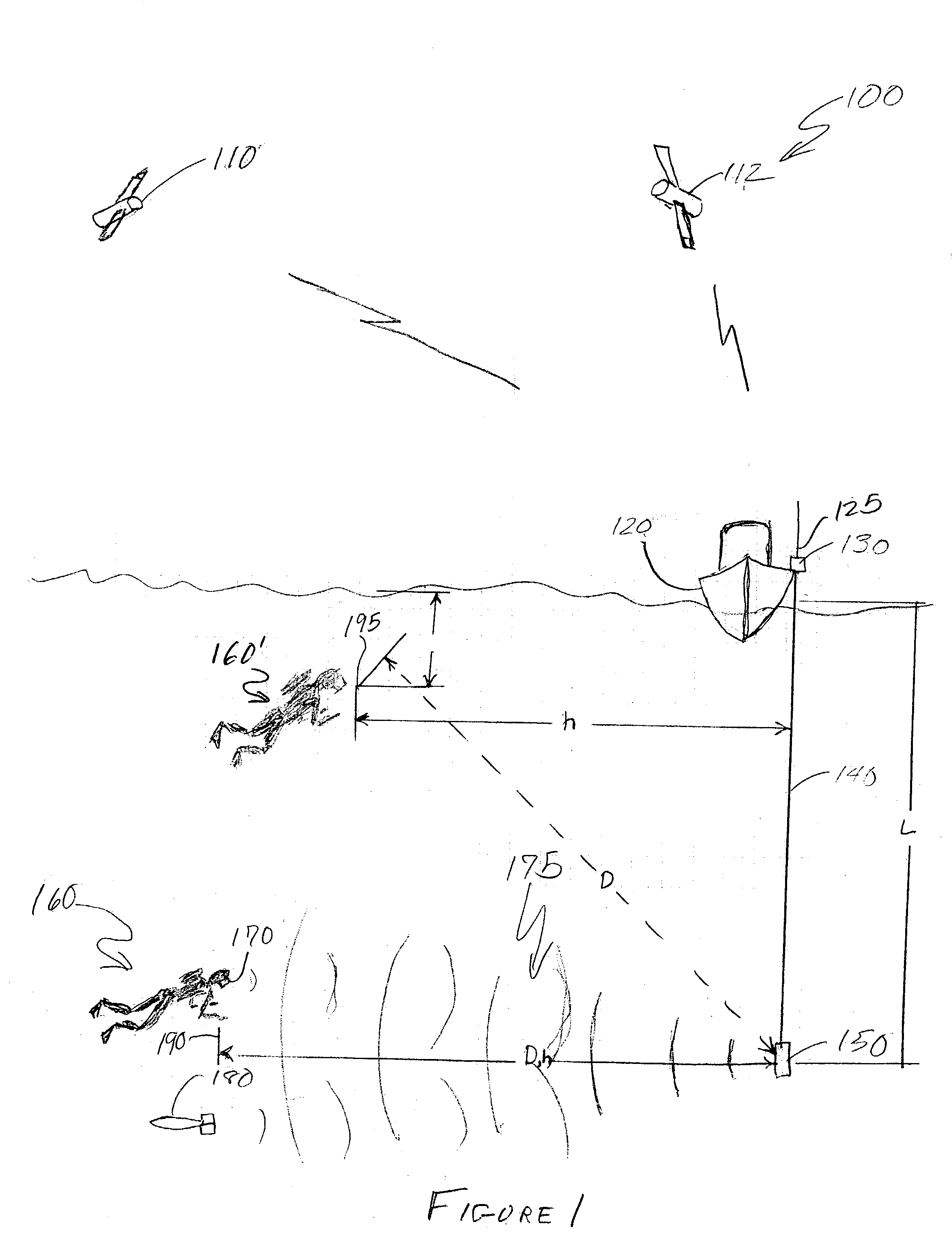
[0041] Many physical factors can contribute to error in the distance and direction calculations being performed by the processor 12, 12' and, as such, may introduce fundamental errors that affects ultimate GPS location calculation. For example, referring to FIG. 1, the sonar ranging described above reflects a distance D which may be at any angle above or below the depth of the transmitter as illustrated by the different positions of divers 160 and 160' which are the same distance from transmitter 150 but at different horizontal distances h parallel to the plane of sonar transmitter 150 and thus at different geographically referenced locations. Further, the measurement of distance D is subject to error due to variations in salinity, temperature or any other parameter that affects the propagation speed of the sonar signal. This embodiment, illustrated in FIG. 5, introduces additional sophistication to the system described in the above embodiments in order to quan...


PUM


Abstract

Underwater position determination is provided by combining sonar-derived ranging data between a sonar receiver and a sonar transmitter with GPS position data to provide geographically-referenced position data accurately representing the position of a sonar receiver carried or worn by a diver or submersible vehicle. Function and accuracy enhancements are provided to compensate for diver and sonar transmitter and depth difference and differences of sonar signal propagation speed as well as several techniques of compensation for change of position of the GPS receiver and for logging diver and/or vehicle path.

Description

[0001] This application claims priority of U.S. Provisional Application Serial No. 60 / 384,716, filed May 31, 2002, which is hereby fully incorporated by reference.[0002] 1. Field of the Invention[0003] The present invention generally relates to position determination utilizing a Global Positioning System (GPS) and, more particularly, to the determination and marking of position in an underwater environment utilizing GPS information.[0004] 2. Description of the Prior Art[0005] Terrestrial Global Positioning Systems (GPS) have been available for several years. Such systems utilize communications with a plurality of satellites which are in known locations (e.g. geostationary orbits) for location of position of a GPS receiver with high accuracy (e.g. usually about six feet or less) on or above the earth's surface. Unfortunately, GPS is not effective underwater due to the inability of GPS signals to properly propagate in water. Current state of the art in underwater use of GPS as a posit...

Claims


Application Information

Patent Timeline
IPC IPC(8): G01S5/00G01S5/14G01S5/18G01S19/19
CPCG01S5/0063G01S5/18G01S19/51G01S19/19G01S19/03
Inventor ESTEP, RANDALL S.
Owner VIAVI SOLUTIONS INC
Why Eureka
Try Eureka