Optical arm for guiding a laser beam on a robot arm

Inactive Publication Date: 2004-04-22
ESTUDIOS DE ING ADAPTADA
View PDF11 Cites 6 Cited by
  • Summary
  • Abstract
  • Description
  • Claims
  • Application Information

AI Technical Summary

Benefits of technology

0022] In accordance with the invention, the parts foreseen with bends have means on the outside to fasten a part provided with some springs that press the mirror against the support lugs defined in the relative window. The fastening of the mirror respect to these parts by means of the pressure of the springs guarantee

Problems solved by technology

The use of a laser combined with a robot poses some important problems concerning the guiding of the beam of light from the laser

Method used


Image

  • Optical arm for guiding a laser beam on a robot arm
  • Optical arm for guiding a laser beam on a robot arm
  • Optical arm for guiding a laser beam on a robot arm

Examples


Example

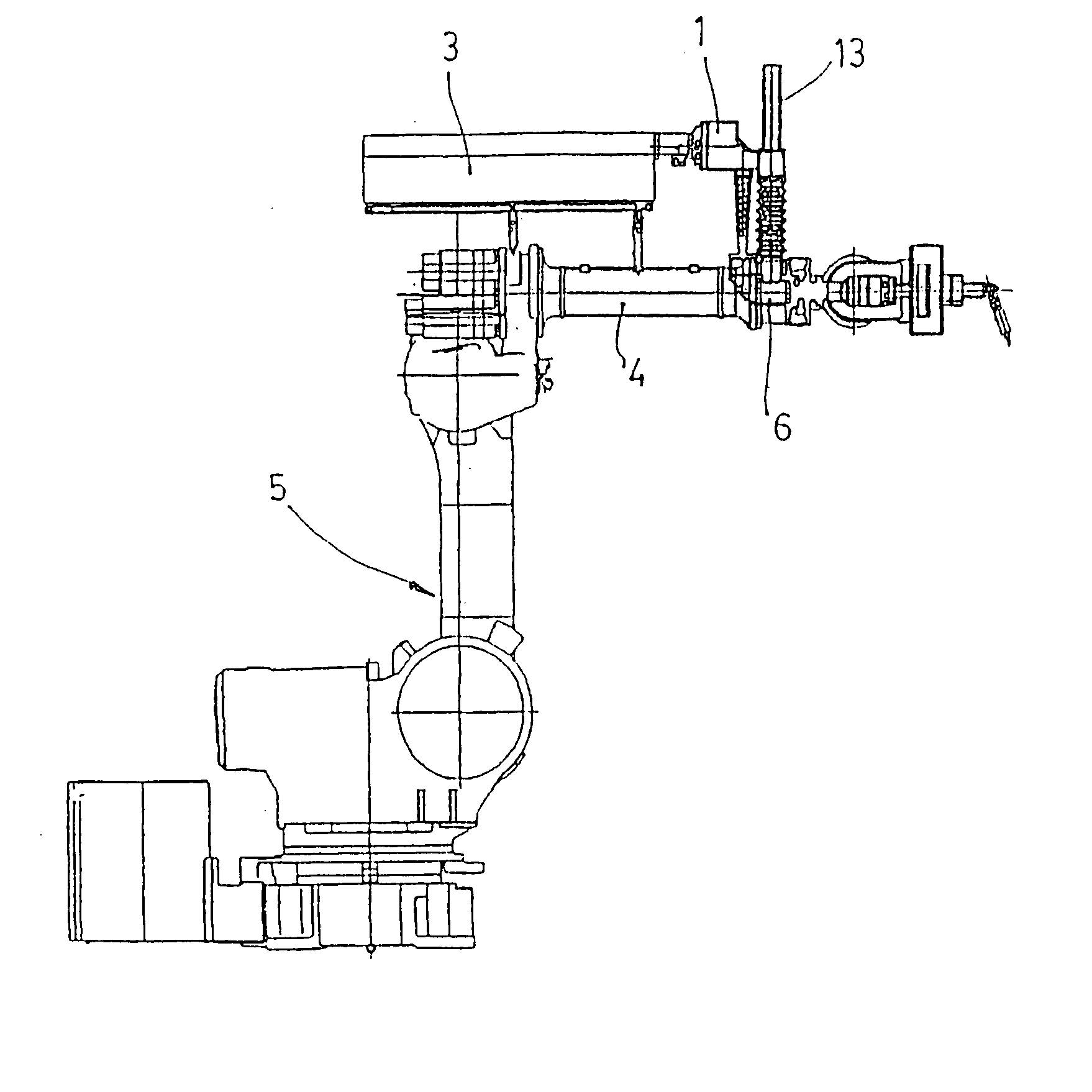
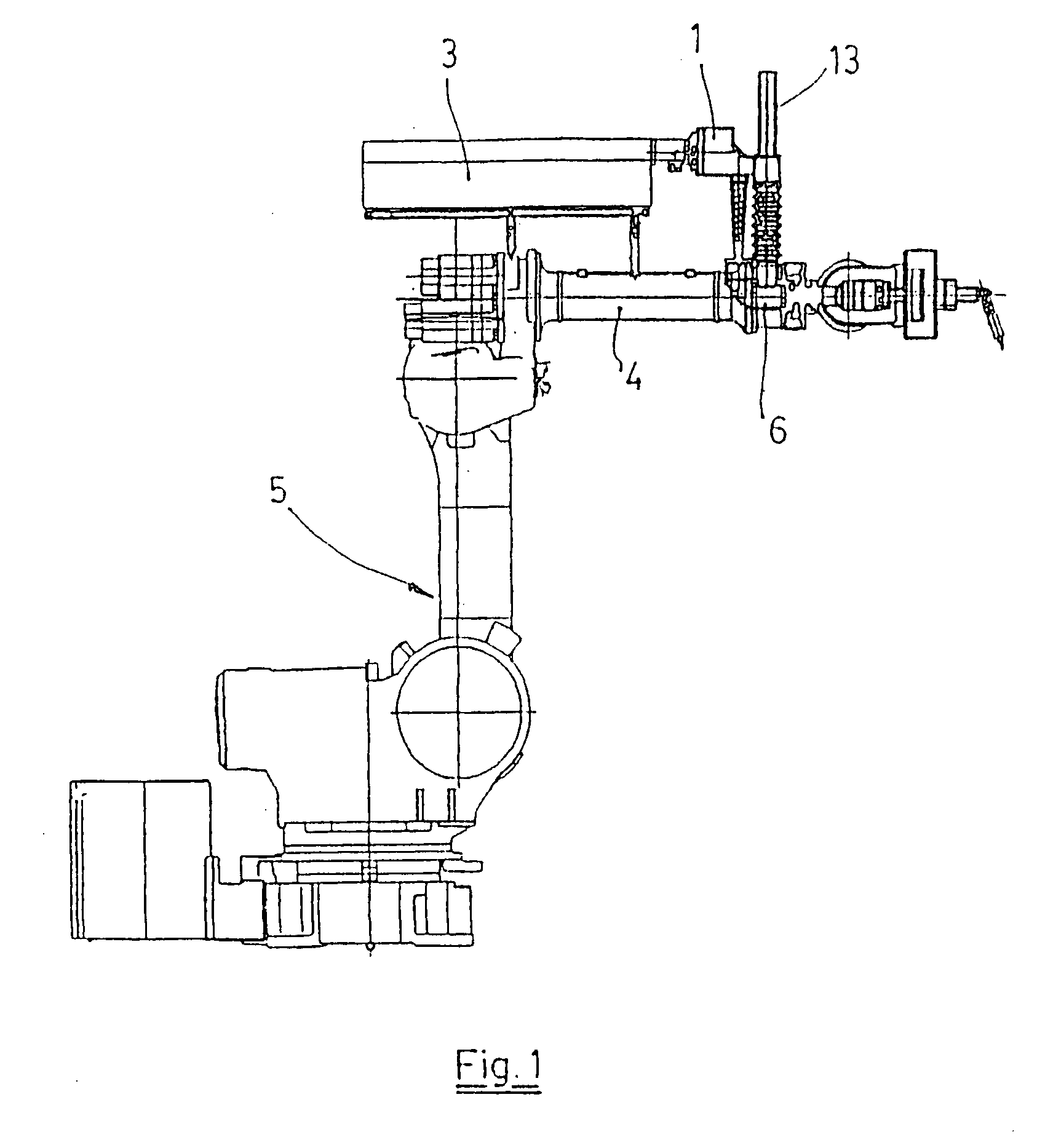
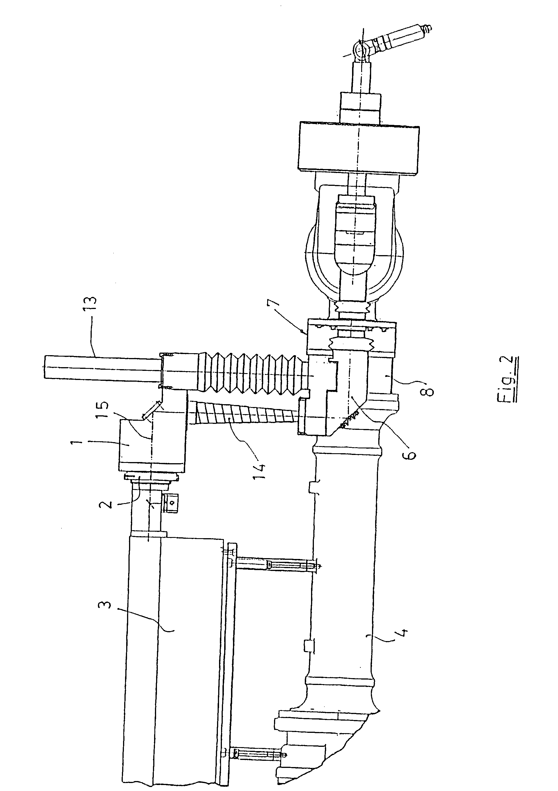
[0007] To solve the problems mentioned, an optical arm applicable to robots targeted by this invention has been designed and which has some constructive peculiarities aimed at permitting its assembly on any traditional robot, occupying minimum space and practically without limiting the mobility of the robot.

[0008] According to this invention, this optical arm is comprised of:

[0009] a first bent tubular part mounted with the possibility of rotation on the outlet from the laser generator secured to the third arm of the robot,

[0010] a second bent tubular part mounted with the possibility of rotation on some support means secured to the fourth arm of the robot,

[0011] some guides that fasten the two bent tubular parts mentioned above, permitting their relative movement and ensuring the permanence of the respective outlets and inlets in opposing positions during the rotation of the fourth arm of the robot,

[0012] an extending tubular element that joins the outlets and the inlets of the afo...


PUM

PropertyMeasurementUnit
Angleaaaaaaaaaa
Diameteraaaaaaaaaa
Elasticityaaaaaaaaaa

Abstract

This optical arm applicable to robots is comprised of: some bent tubular parts (1, 6, 16, 18), a straight tubular length (21) and an outlet part (23), coupled together with the possibility of rotation; also including some means (7) to secure the optical arm to a robot (5). The bent tubular part (1) is mounted with the possibility of rotation on the outlet (2) of a laser generator (3) secured to the third arm (4) of the robot (5). Parts (1, 6, 16 and 18) have a window (28), in each bend, equipped with some inner lugs (28) which a mirror (29) is pressed on to by means of some springs (33) foreseen with a removable part (32).

Description

OBJECT OF THE INVENTION[0001] This invention refers to an optical arm designed to be coupled to a robot and to adapt to the robot's movements ensuring the guidance of a beam of light from a laser generator to an outlet part.[0002] Currently the use of laser in different applications is normal practice, as well as the use of robots to guide the beam of light in the desired direction.[0003] The use of a laser combined with a robot poses some important problems concerning the guiding of the beam of light from the laser generator to a outlet part or applicator, as the optical arm used to guide it must be able to accompany the robot in its movements.[0004] To achieve this, some of the currently used optical arms are comprised of a series of tubular lengths which are placed parallel to each of the robot arms and which are joined together by means of some articulations, whose rotation axes coincide with each one of the rotation axes of the robot, these articulations including a mirror resp...

Claims


Application Information

Patent Timeline
IPC IPC(8): B23K26/08B23K26/10B25J19/00
CPCB25J19/0037B23K26/0884
Inventor VILA PAPELL, ENRIC
Owner ESTUDIOS DE ING ADAPTADA
Why Eureka
Try Eureka