Support bra for ultrasonic breast scanner

Inactive Publication Date: 2004-04-29
ALFRED E MANN INST FOR BIOMEDICAL ENG AT THE UNIV OF SOUTHERN CALIFORNIA
View PDF48 Cites 71 Cited by
  • Summary
  • Abstract
  • Description
  • Claims
  • Application Information

AI Technical Summary

Benefits of technology

0022] The diameter of the open end of the cup may be slightly less than the diameter of the opening in the ultrasonic sca

Problems solved by technology

Unfortunately, x-rays can be harmful to the patient.
This can create discomfort.
Unfortunately, the breast may move during the scannin

Method used


Image

  • Support bra for ultrasonic breast scanner
  • Support bra for ultrasonic breast scanner
  • Support bra for ultrasonic breast scanner

Examples


Embodiment Construction

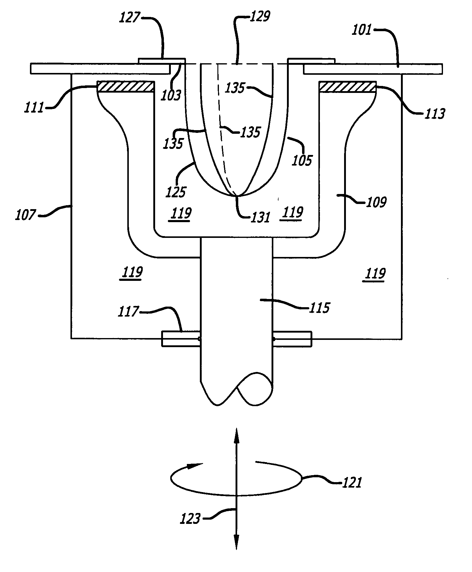
[0033] FIG. 1 shows portions of an ultrasonic scanner with a support bra and contoured coronal plane locator wires.

[0034] As shown in FIG. 1, a tabletop 101 on which a female patient may lie may include an opening 103 into which a bra-like receptacle 105 may be inserted. Directly below the opening 103 may be a stationary chamber 107.

[0035] The tabletop 101 may be long enough and wide enough to accommodate varies sizes of female patients. Similarly, the opening 103 may be large enough to accommodate various sizes of breasts that will be placed within it. A reduction ring (not shown) may be inserted in the opening 103 to better support female subjects with smaller breasts.

[0036] The receptacle 105 may include a contoured cup 125 attached to an annular ring 127.

[0037] The contoured cup 125 may include an open end 129 into which the breast may be inserted and a narrowed end 131 into which the nipple of the breast may be inserted.

[0038] The contoured cup 125 may be made of material that ...


PUM


Abstract

A receptacle for supporting a breast during ultrasonic scanning. The receptacle may include a contoured cup made of material that is substantially transparent to acoustical energy and have an open end into which the breast may be inserted and a narrowed end to receive a nipple of the breast. The receptacle may include spaced-apart elongated members, each made of material that is not substantially transparent to acoustical energy and each being mechanically coupled to the open end and to the narrow end of the cup. A fluid pump, impedance matching and a contoured tabletop are also disclosed.

Description

[0001] This application is based upon and claims priority to U.S. Provisional Application Serial No. 60 / 396,516, entitled "Support Bra for Ultrasonic Breast Scanner," filed Jul. 16, 2002, the entire content of which is incorporated herein by reference.BACKGROUND OF INVENTION[0002] 1. Field of Invention[0003] This application relates to breast mammography and, more particularly, ultrasonic breast scanners.[0004] 2. Description of Related Art[0005] Breast mammography has traditionally used x-ray techniques. Unfortunately, x-rays can be harmful to the patient. The breast is also frequently compressed during the procedure. This can create discomfort.[0006] Ultrasonic scanning has been proposed as an alternate approach. The breast is dangled in a fluid bath. An ultrasonic transmitter and cooperating ultrasonic receiver are rotated around the breast to scan a series of stacked coronal imaging planes. These stacked planes are then used to generate data representative of a three-dimensional...

Claims


Application Information

Patent Timeline
IPC IPC(8): A61BA61B8/00A61B8/08
CPCA61B8/406A61B8/0825
Inventor MARMARELIS, VASILIS Z.
Owner ALFRED E MANN INST FOR BIOMEDICAL ENG AT THE UNIV OF SOUTHERN CALIFORNIA
Why Eureka
Try Eureka