
Motion vector coding method and motion vector decoding method

a technology of motion vector and coding method, which is applied in the field of motion vector coding method and motion vector decoding method, can solve the problems of not being able to transmit video shot by tv cameras directly through isdn, not being able to code neighboring blocks, and not being able to achieve the effect of high practicability

Active Publication Date: 2004-05-06
PANASONIC INTELLECTUAL PROPERTY CORP OF AMERICA
View PDF8 Cites 53 Cited by
  • Summary
  • Abstract
  • Description
  • Claims
  • Application Information

AI Technical Summary

Benefits of technology

The present invention is a motion vector coding method and a motion vector decoding method for efficient coding and decoding of motion vectors in moving pictures. The method uses a predictive motion vector derived from neighboring blocks to improve coding efficiency and accuracy. The motion vector coding and decoding methods involve a judgment step, a prediction step, a coding control unit, and a motion vector storage unit. The invention also includes a motion vector estimation unit, a mode selection unit, and a coding control unit for efficient motion vector coding and decoding. The technical effects of the invention include improved coding efficiency, accuracy of predictive motion vectors, and improved practical value of motion vectors.

Problems solved by technology

However, when calculating the amount of information contained in each of the aforementioned information media as the amount of digital information, while the amount of information per character is 1.about.2 bytes, the amount of information to be required for voice is 64 Kbits or over per second (telephone quality), and 100 Mbits or over per second for moving pictures (current television reception quality), and it is not realistic for the aforementioned information media to handle such an enormous amount of information as it is in digital form.
For example, although video phones are already in the actual use via Integrated Services Digital Network (ISDN) which offers a transmission speed of 64 Kbps / s.about.1.5 Mbps / s, it is not practical to transmit video shot by television cameras directly through ISDN.
However, there are cases where motion vectors of neighboring blocks are not coded.
So, there is a problem of causing an inaccurate predictive value of a motion vector when coding the motion vector, and thus causing lower coding efficiency.

Method used


Image

  • Motion vector coding method and motion vector decoding method
  • Motion vector coding method and motion vector decoding method
  • Motion vector coding method and motion vector decoding method

Examples


first embodiment

[0062] A moving picture coding apparatus in the present invention will be explained with reference to the figures.

[0063] FIG. 6 is a block diagram of the moving picture coding apparatus in the first embodiment of the present invention.

[0064] This moving picture coding apparatus 100 aims at improving coding efficiency by improving accuracy of a predictive value of a motion vector, and includes a frame memory 101, a difference calculation unit 102, a prediction error coding unit 103, a bit stream generation unit 104, a prediction error decoding unit 105, an addition unit 106, a frame memory 107, a motion vector estimation unit 108, a mode selection unit 109, a coding control unit 110, switches 111.about.115, a motion vector storage unit 116 and a motion vector coding unit 117.

[0065] The frame memory 101 is a picture memory for holding inputted pictures on a picture-by-picture basis, and reorders the pictures inputted and obtained in order of time into coding order for output. The pict...

second embodiment

[0150] A moving picture decoding apparatus 700 in the second embodiment of the present invention will be explained with reference to the figures.

[0151] FIG. 14 is a block diagram showing the structure of the moving picture decoding apparatus 700 in the second embodiment of the present invention.

[0152] The moving picture decoding apparatus 700 as shown in FIG. 14 decodes moving pictures coded by the moving picture coding apparatus 100 in the first embodiment, and includes a bit stream analysis unit 701, a prediction error decoding unit 702, a mode decoding unit 703, a motion compensation decoding unit 705, a motion vector storage unit 706, a frame memory 707, an addition unit 708, switches 709 and 710, and a motion vector decoding unit 711.

[0153] The bit stream analysis unit 701 extracts various data from the inputted bit stream. Here, various data includes information on coding mode, information on motion vectors, and so on. The extracted coding mode information is outputted to the ...

third embodiment

[0213] In addition, if a program for realizing the motion vector coding method or the motion vector decoding method as shown in each of the above-mentioned embodiments is recorded on a storage medium such as a flexible disk, it becomes possible to perform the processing as shown in each of the above embodiments easily in an independent computer system.

[0214] FIG. 18 is an illustration of a storage medium that stores a program for realizing the motion vector coding method and the motion vector decoding method executed by the moving picture coding apparatus 100 in the first embodiment and the moving picture decoding apparatus 200 in the second embodiment by a computer system.

[0215] FIG. 18B shows the front view and the cross-sectional view of the appearance of a flexible disk FD, and a disk FD1, and FIG. 18A shows an example of a physical format of the disk FD1 as a recording medium itself.

[0216] The disk FD1 is contained in a case F, a plurality of tracks Tr are formed concentrically...


PUM


Abstract

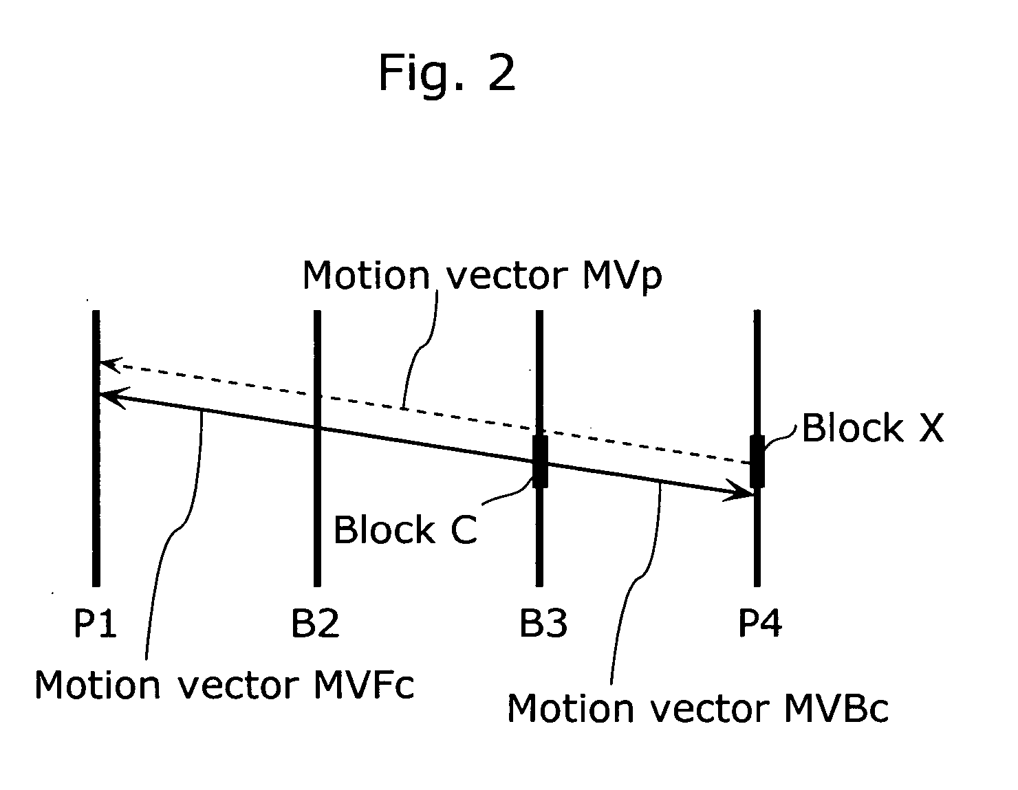
A motion vector coding unit 117 executes processing including a neighboring block specification step (S100) of specifying a neighboring block which is located in the neighborhood of a current block; a judgment step (Steps S102, S104) of judging whether or not the neighboring block has been coded using a motion vector of another block; a prediction step (S106, S108) of deriving a predictive motion vector of the current block using a motion vector calculated from the motion vector of the other block as a motion vector of the neighboring block; and a coding step (S110) of coding the motion vector of the current block using the predictive motion vector.

Description

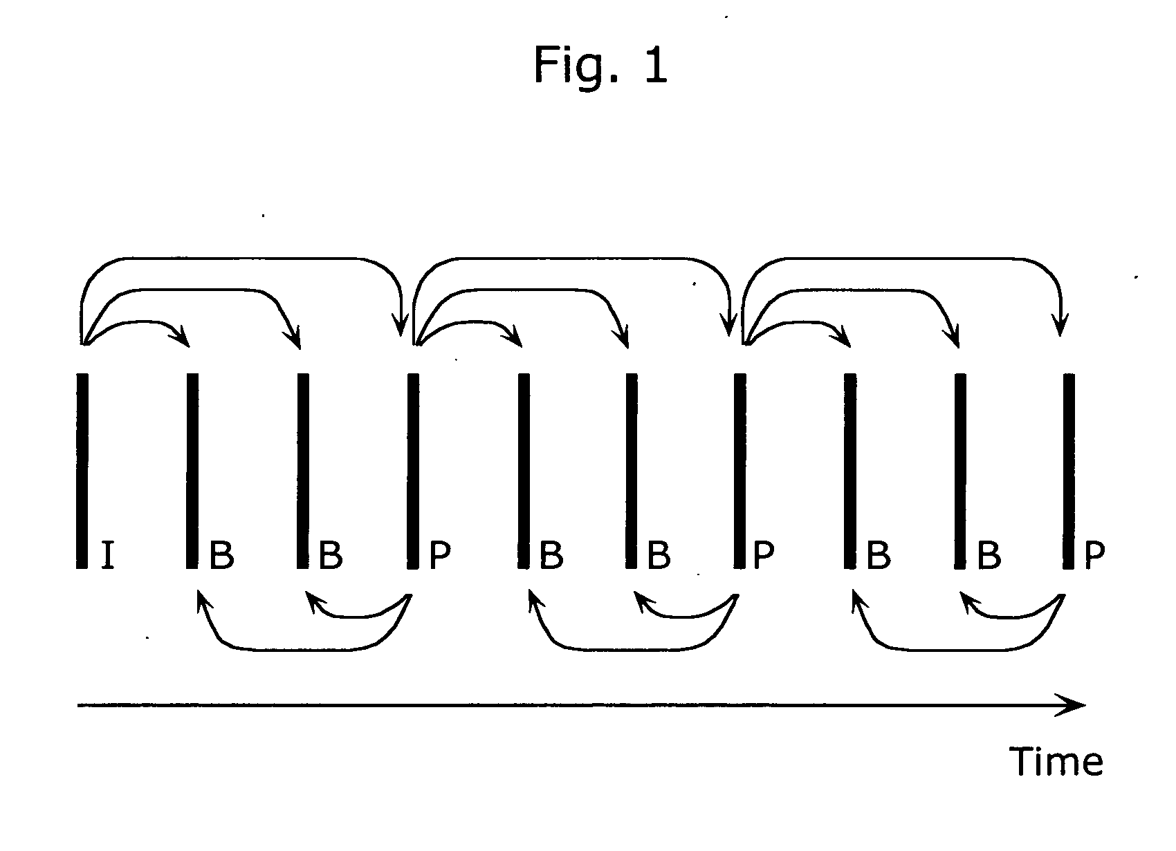
[0001] The present invention relates to a motion vector coding method and a motion vector decoding method using inter picture prediction coding.[0002] In the age of multimedia which integrally handles audio, video and other information, existing information media, i.e., newspapers, magazines, televisions, radios, telephones and other means through which information is conveyed to people, have recently come to be included in the scope of multimedia. Generally, multimedia refers to something that is represented by associating not only characters, but also graphics, voices, and especially pictures and the like together, but in order to include the aforementioned existing information media in the scope of multimedia, it appears as a prerequisite to represent such information in digital form.[0003] However, when calculating the amount of information contained in each of the aforementioned information media as the amount of digital information, while the amount of information per characte...

Claims


Application Information

Patent Timeline
Patent Type & Authority Applications(United States)
IPC IPC(8): H03M7/36H04N19/105H04N19/51H04N19/423H04N19/50H04N19/61H04N19/625
CPCH04N19/521H04N19/533H04N19/52H04N19/50H04N19/51H04N19/513H04N19/61H04N19/593H04N19/517H04N19/577H04N19/137H04N19/139H04N19/176H04N19/537H04N19/56H04N19/105H04N19/172A61B5/022A61B5/0261A61B5/7207H04N19/184
Inventor KONDO, SATOSHIKADONO, SHINYAHAGAI, MAKOTOABE, KIYOFUMI
Owner PANASONIC INTELLECTUAL PROPERTY CORP OF AMERICA
Learn More