Clamping nut for an osteosynthesis device

Active Publication Date: 2004-05-13
SCIENTX
View PDF12 Cites 79 Cited by
  • Summary
  • Abstract
  • Description
  • Claims
  • Application Information

AI Technical Summary

Benefits of technology

0006] The object of the present invention is thus to remedy the above-specified drawbacks by proposing a technique enabling an interverteb

Problems solved by technology

Although an anchor screw of the type having a spherical joint makes it possible to achieve an adaptable relative angle between said screw and the intervertebral connection element, it must be considered that making a spherical joint on an anchor screw contributes to weakening it by including a moving interface that can even lead to the intervertebral connection element breaking.
Furthermore, it has been found that even in the presence of an anchor screw of the type having a spherical joint, the threaded shank does not always extend to pr

Method used


Image

  • Clamping nut for an osteosynthesis device
  • Clamping nut for an osteosynthesis device
  • Clamping nut for an osteosynthesis device

Examples


Example

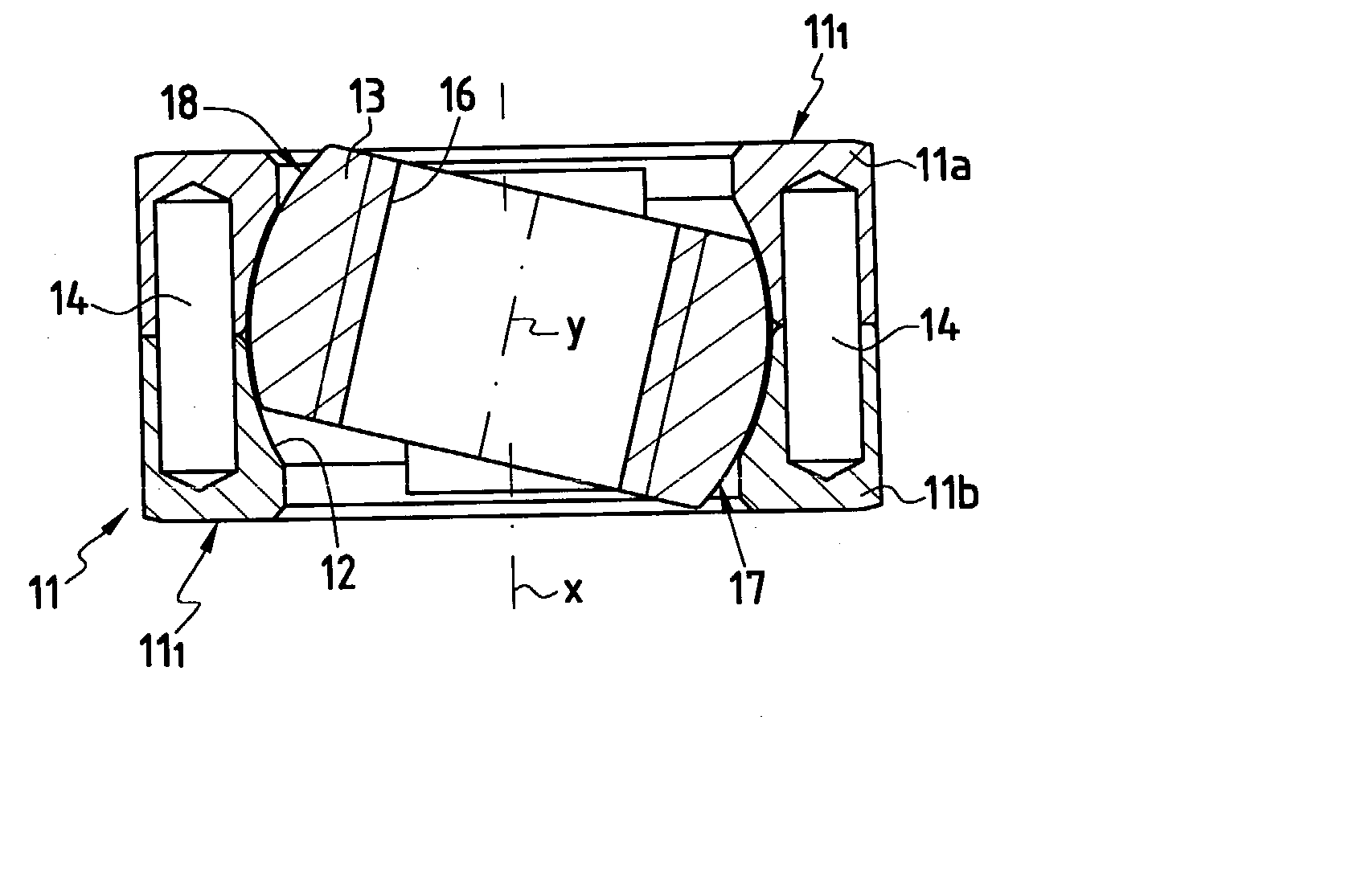
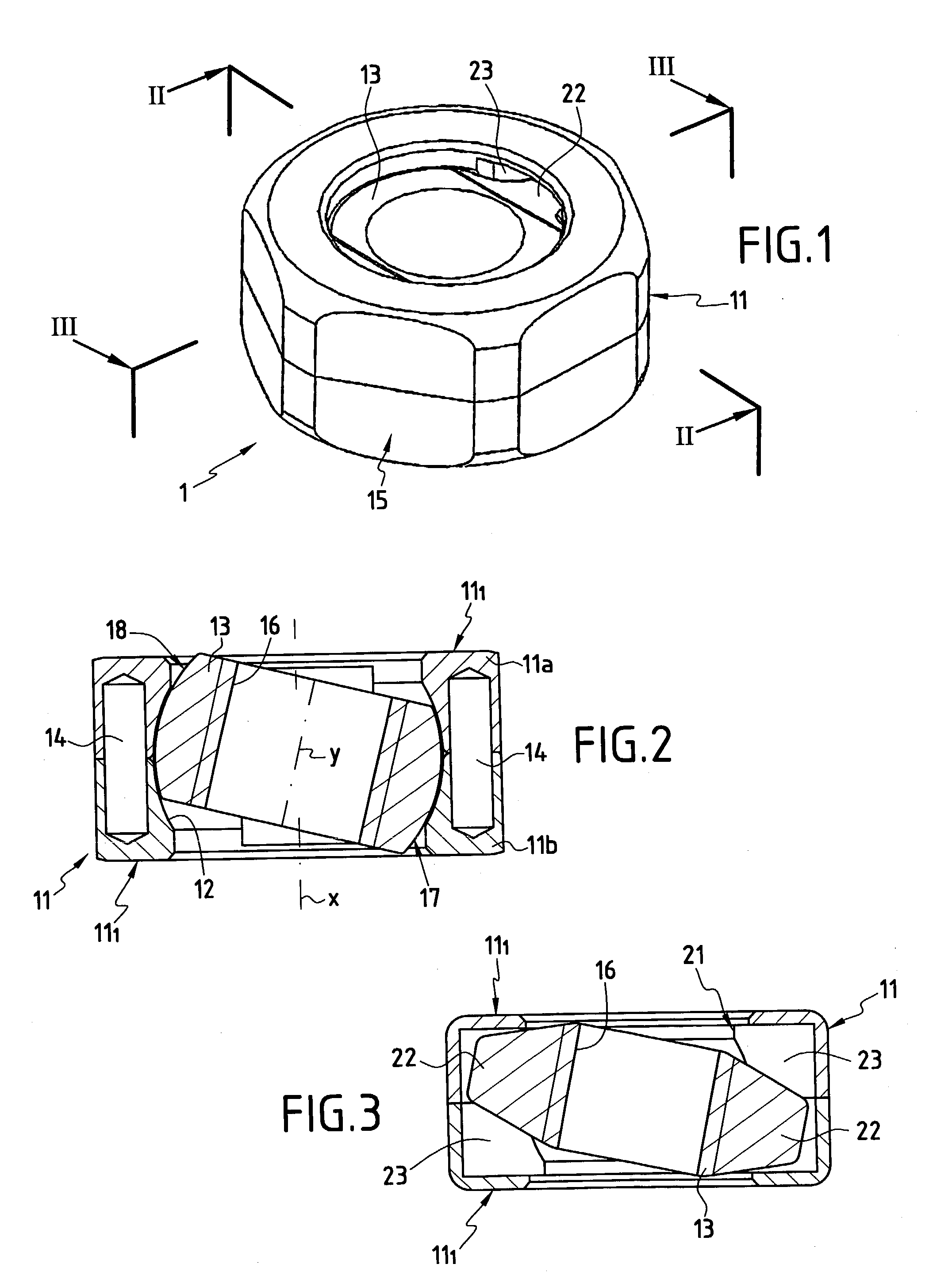
[0025] FIGS. 1 to 3 show a clamping nut 1 in accordance with the invention for use in an osteosynthesis device 2 for the spine.

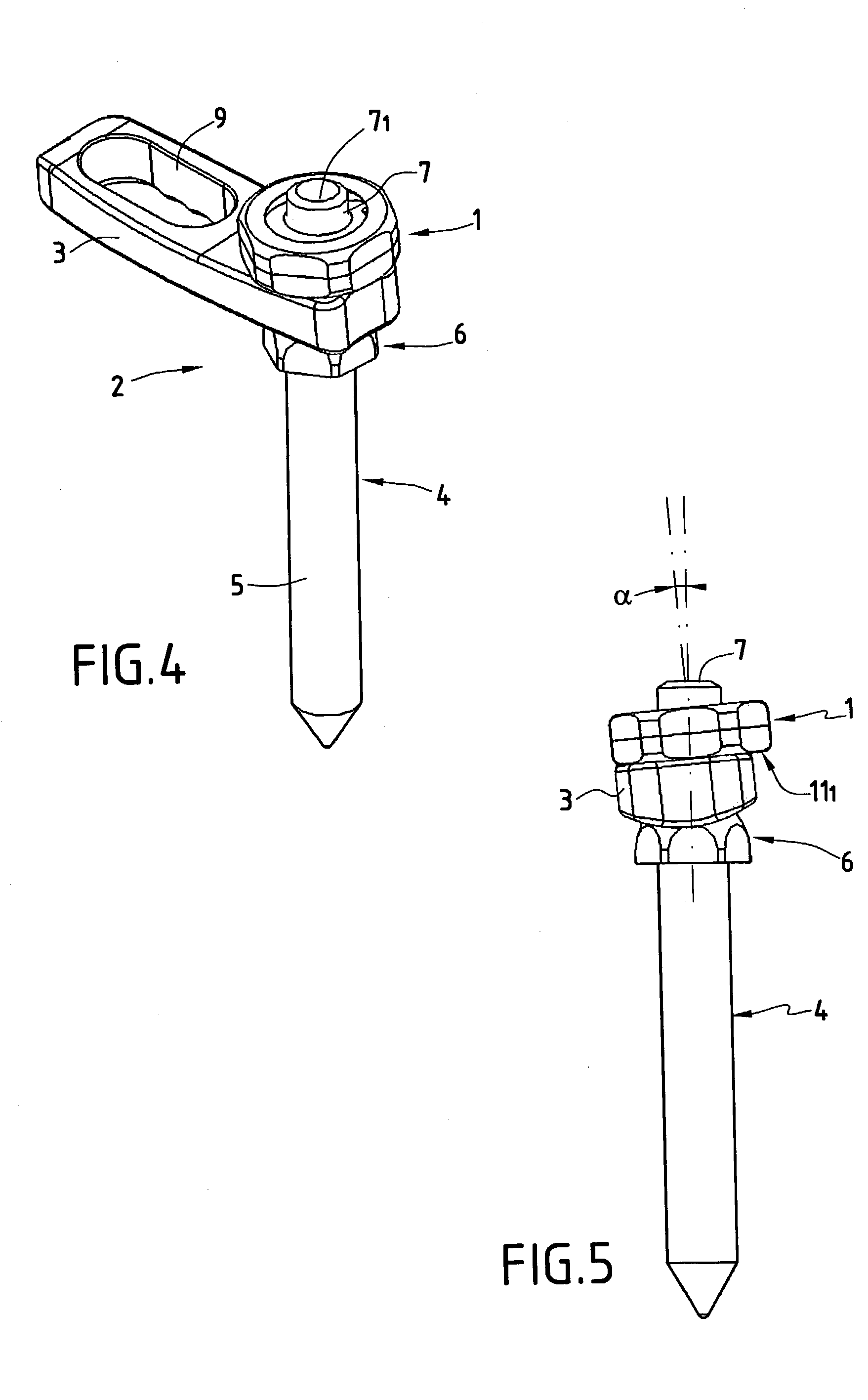
[0026] In the example shown in FIGS. 4 and 5, the osteosynthesis device 2 comprises an intervertebral connection element 3 such as a plate in the example shown together with at least one osteosynthesis appliance 4 in the general sense capable of being made in various known ways. The osteosynthesis appliance 4 thus constitutes, for example, a bone anchor element in the form of a hook or as shown in the drawings, in the form of an anchor screw. Such an osteosynthesis appliance 4 can also be in the form of a plate or of an intermediate connection element.

[0027] In the example shown, the osteosynthesis appliance 4 forming a bone anchor screw comprises a threaded portion 5 and a head 6 from which there extends a threaded shank 7. In the example shown, the threaded shank 7 extends substantially in line with the threaded portion 5. In known manner, the intervertebr...


PUM


Abstract

A clamping nut suitable for co-operating with a threaded shank of an osteosynthesis appliance, the nut comprising an annular body and a tapped bore for cooperating with the threaded shank, the annular body being provided with turning means and with a transverse bearing face. According to the invention, the nut further comprises: a ring mounted in a housing of the annular body and provided internally with the tapped bore, and cooperating externally with the annular body to form a spherical joint; and means for preventing relative turning between the ring and the annular body.

Description

[0001] The present invention relates to the technical field of osteosynthesis, in particular of the spine, and it relates more particularly to a clamping nut used in osteosynthesis devices for the spine.[0002] More precisely, the invention provides a clamping nut designed to present an angle relative to an osteosynthesis appliance in the general sense.[0003] One of the known applications for the invention relates to devices designed to correct and hold a set of vertebrae in a determined position. In this application, such a device comprises an intervertebral connection element such as a plate or a rod suitable for being held in position by bone anchor elements such as screws implanted in the vertebrae. Each bone anchor element is provided with a head, and a threaded shank for mounting the plate which has through holes. The plate is engaged on the threaded shank via a through hole and the portion of the shank that projects from the plate is used for receiving a clamping nut.[0004] Gi...

Claims


Application Information

Patent Timeline
IPC IPC(8): A61B17/70A61B17/80A61B17/86
CPCA61B17/7059A61B17/8665A61B17/8033
Inventor CARLI, OLIVIER
Owner SCIENTX
Why Eureka
Try Eureka