
Implantable lead/electrode delivery measurement and feedback system

Active Publication Date: 2010-04-01
PACESETTER INC
View PDF31 Cites 55 Cited by
  • Summary
  • Abstract
  • Description
  • Claims
  • Application Information

AI Technical Summary

Benefits of technology

[0009]Embodiments of the invention provide a lead and lead implantation system and methods of use of a lead system to more effectively position and fix patient leads in desired positions. In general, at least a portion of a lead is configured to be attached or otherwise engaged with patient tissue to restrain unintended further movement of the lead to facilitate maintenance of the lead at the desired location. In various embodiments, a lead fixation structure can be combined with sensing and/or therapy delivery functionality of the lead and in other embodimen

Problems solved by technology

However, in general, such information and / or therapy cannot readily or conveniently be obtained / provided via periodic intermittent clinical observations.
In a number of implementations, however, there exist difficulties with existing implantable device systems and methods for implantation of such systems in accurately placing and fixing patient leads in desired locations.
For example, implantation procedures are frequently performed in a manner such that a fixation location is not easily directly observable by the clinician performing the implantation procedure.
One limitation with fluoroscopy however is that it is at least sometimes difficult to accurately discern soft tissue boundaries.
This can make it difficult for a clinician to view whether or not an implanted device is at a desired position with respect to target tissue.
Another difficulty with fluoroscopy in positioning of implantable structures is that the obtained image is a two-dimensional image.
Thus, while fluoroscopy may be able to relatively accurately provide location information to the clinician in two dimensions orthogonal to the viewing dimension, three-dimensional location information or location information generally along or parallel to the fluoroscopy viewing dimension is less readily discernible.
This lack of three-dimensional or “depth” location data can complicate accurate positioning of the implantable structures at the desired location.
In addition, as fluoroscopes employ X-ray sources to irradiate the patient tissue and obtain a fluoroscope image, use of fluoroscopy exposes the patient to highly undesirable ionizing radiation.

Method used


Image

  • Implantable lead/electrode delivery measurement and feedback system
  • Implantable lead/electrode delivery measurement and feedback system
  • Implantable lead/electrode delivery measurement and feedback system

Examples


Embodiment Construction

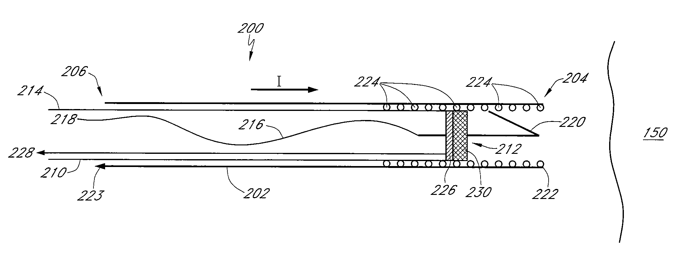
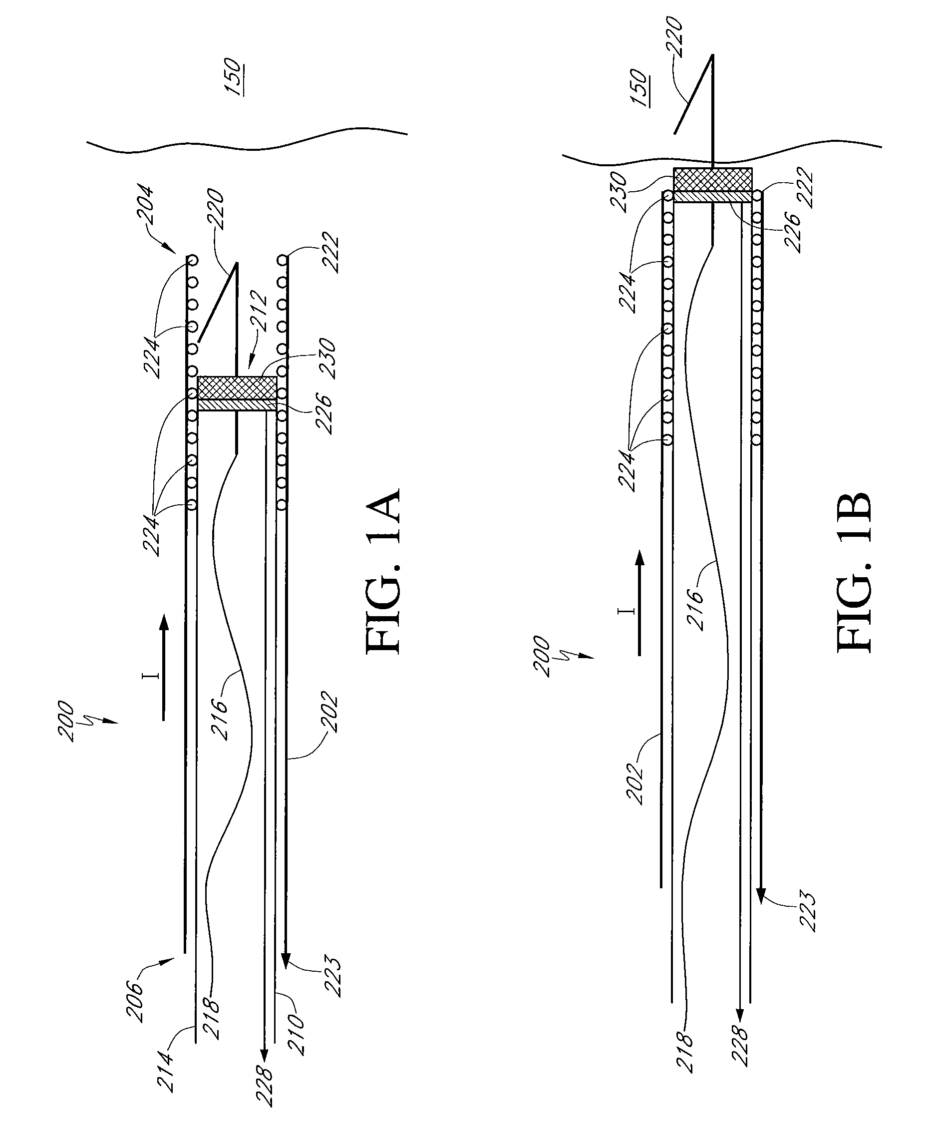
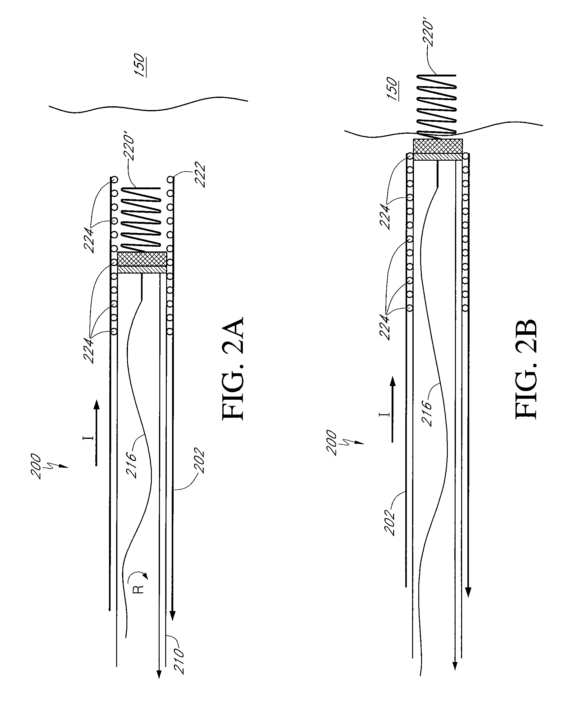
[0028]FIG. 1 illustrates a schematic side section view of one embodiment of a lead implantation system 200. The lead implantation system 200 is configured to introduce one or more patient leads to a desired implantation location and to facilitate fixation or securing of the patient leads to target tissue 150. In various embodiments, the system 200 can be adapted to implant leads configured solely for delivery of therapy, leads configured solely for sensing or monitoring, and / or leads adapted to perform both delivery of therapy and monitoring and sensing of the patient. In various embodiments, the system 200 can be further adapted to implant leads configured for delivery of therapeutic agents, and / or delivery of therapeutic stimulation. In one particular embodiment, the system 200 is adapted to implant leads configured to provide therapy for one or more cardiac arrhythmias which can include pacing therapy, cardioversion therapy and / or defibrillation therapy.

[0029]In one embodiment, t...


PUM


Abstract

A lead implantation system with an introducer, a lead configured to engage with the introducer such that the introducer can convey the lead to a desired internal target location, and at least one sensor. The sensor is adapted to generate an indicator of desired engagement of the system with the desired target tissue location prior to engagement of the lead with the target tissue. Also a method of implanting an implantable patient lead including advancing a lead implantation assembly towards a desired target location along an introduction axis and monitoring at least one indicator of lead implantation assembly position along the lead introduction axis. At least one indicator can be generated by the lead implantation assembly. Advancing of the lead introduction assembly can be halted when the monitoring indicates contact with the desired target tissue. The patient lead can then be advanced towards the target tissue and fixed to the target tissue.

Description

CROSS REFERENCE TO RELATED APPLICATIONS[0001]This application contains subject matter that is related to copending U.S. patent application Ser. No. 11 / 456,825, filed Jul. 11, 2006, titled “Apparatus and Method for Electrode Insertion in Heart Tissue” (Attorney Docket A06P1066).FIELD OF THE INVENTION[0002]This invention relates to the field of implantable therapy delivery and / or monitoring systems and to systems and methods of more accurately and reliably performing implantation operations to place structures at desired locations.BACKGROUND OF THE INVENTION[0003]A variety of medical conditions exist for which ongoing delivery of therapy and / or extended monitoring of the patient's condition is indicated. For example, patients can exhibit medical conditions which indicate extended periods of delivery of therapeutic agents / medications. Patients may also exhibit medical conditions indicating extended stimulation of nerve tissue. Patients may also exhibit a variety of cardiac arrhythmias ...

Claims


Application Information

Patent Timeline
IPC IPC(8): A61N1/05
CPCA61N1/08A61N1/05
Inventor SILIPO, ENZORYU, KYUNGMOOBORNZIN, GENE A.POORE, JOHN W.VICTORINE, KEITHSOMOGYI, ZOLTANPERERA, NALIN
Owner PACESETTER INC
Learn More