

Bending device, control device, and medical instrument
- Summary
- Abstract
- Description
- Claims
- Application Information
AI Technical Summary
Benefits of technology
Problems solved by technology
Method used
Image

Examples
embodiment 1
[0048]Embodiments of the present invention will be described below in detail based on FIGS. 1 to 6, 18, and 19.
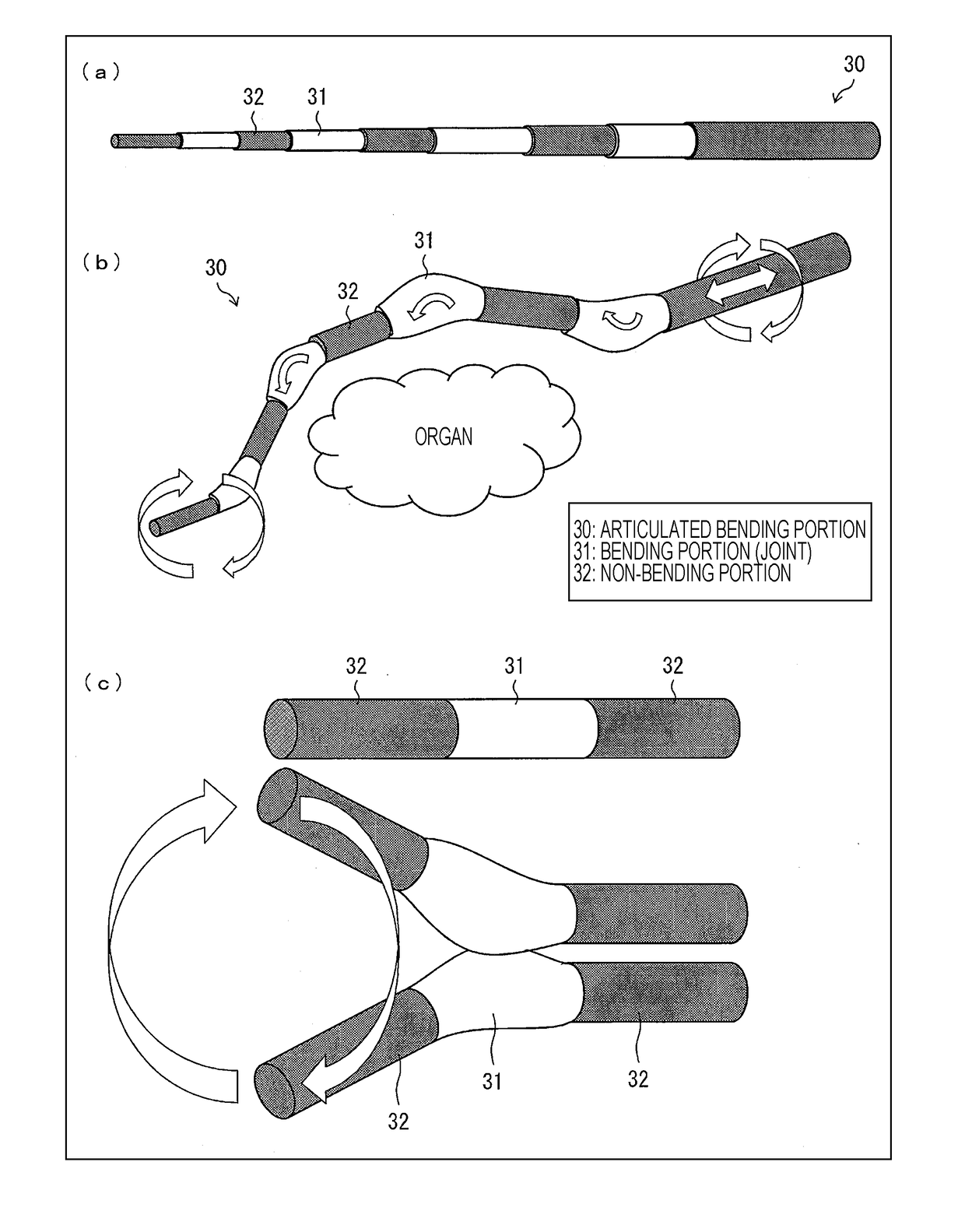
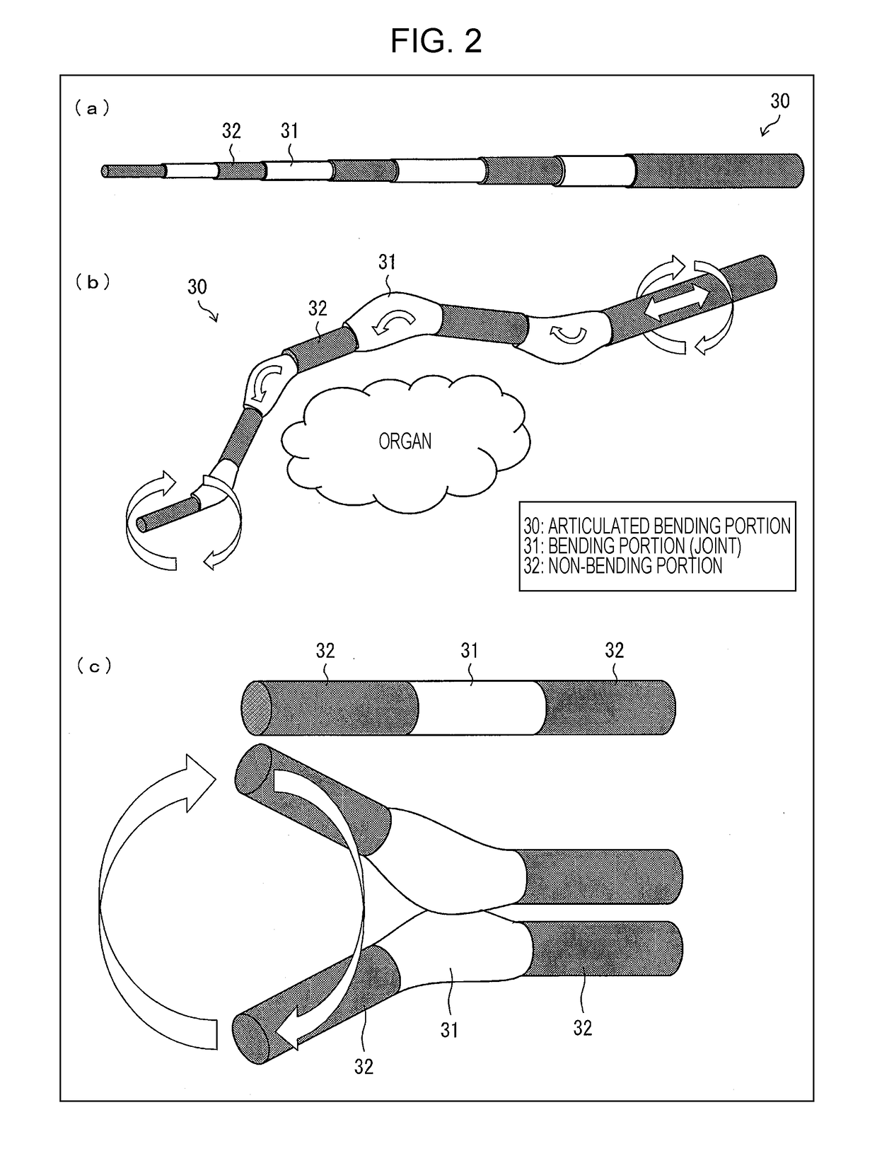
[0049]The bending device according to the present invention is a medical instrument to which a medical device can be attached at the distal end. While an articulated bending portion 30 having multiple deformable bending portions 31 (joints) will be described as an example of the bending device according to the present invention, the bending device according to the present invention includes a bending device with a single joint as well.
(Overview of the Medical Instrument)
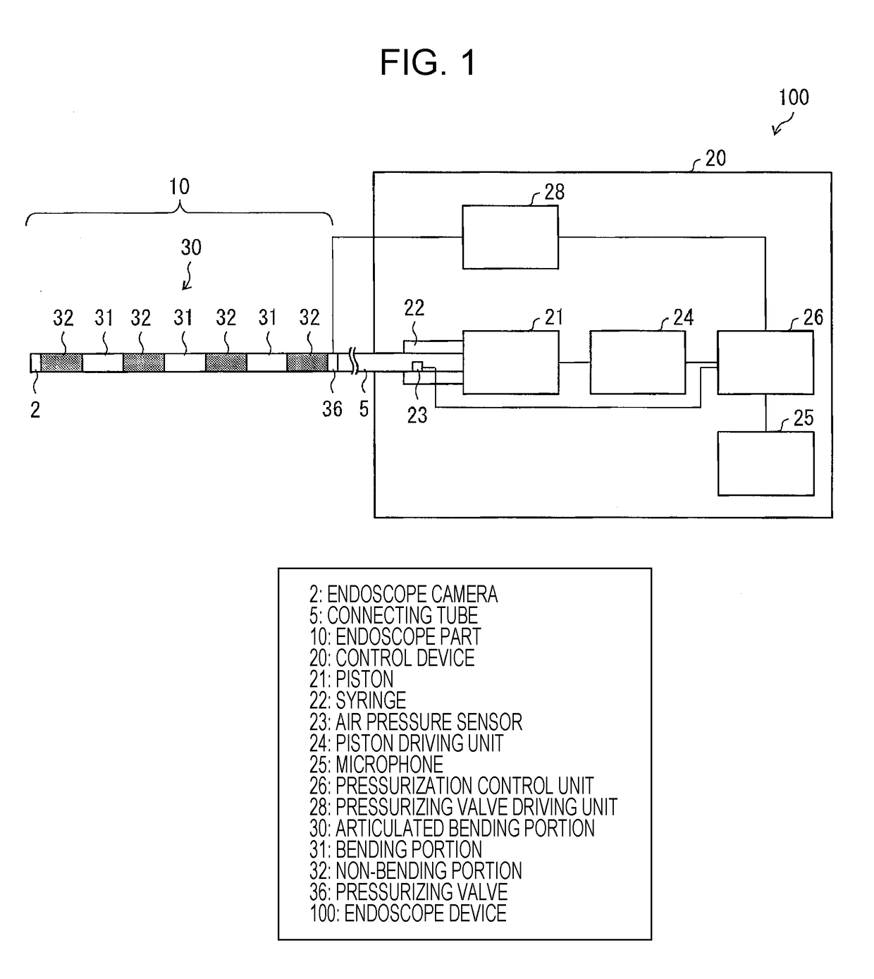
[0050]FIG. 1 shows the configuration of an endoscope device as an example of a medical instrument including elastic tubes according to an embodiment of the present invention. In FIG. 1, an endoscope device 100 (a medical instrument) includes an endoscope part (medical instrument part) 10 and a control device 20. The control device 20 drives and controls the endoscope part 10. The control device 20 will be de...
embodiment 2
[0122]Another embodiment of the present invention will be described below based on FIGS. 7 to 9. For the sake of description, components having the same functionality as ones described in the previous embodiment are denoted with the same reference numerals and description of such components is omitted.
[0123]Embodiment 1 mainly described a movable mechanism with a single bending portion in detail, while Embodiment 2 will describe a movable mechanism that operates by coordinating two bending portions in combination.
(Overview of the Articulated Bending Portion)
[0124]FIG. 7 shows an example of a movable mechanism that operates by coordinating two bending portions in combination. While the configuration with four elastic tubes 1a to 1d forming the articulated bending portion is similar to Embodiment 1, the position of each of the elastic tubes 1a to 1d is interchanged with the opposite tube in the non-bending portion 32 as illustrated in FIG. 7.
[0125]FIG. 8(a) is a cross-sectional view s...
embodiment 3
[0135]Still another embodiment of the present invention will be described below based on FIG. 10. For the sake of description, components having the same functionality as ones described in the previous embodiments are denoted with the same reference numerals and description of such components is omitted.
[0136]Embodiments 1 and 2 mainly detailed a movable mechanism that has one or two bending portions, particularly in connection with application to a distal end portion having a camera attached thereon, while Embodiment 3 will describe a movable mechanism that operates with further increased bending portions in combination.
(Overview of the Articulated Bending Portion)
[0137]FIG. 10 shows an example of a configuration with bending portions using the movable mechanism that operates with one or two bending portions in combination described in Embodiments 1 and 2 for the distal end portion having a camera attached thereon and using the configuration described in Embodiment 2 in the middle ...
PUM
 Abstract
Description
Claims
Application Information