

In-line inspection of ophthalmic device with auto-alignment system and interferometer
- Summary
- Abstract
- Description
- Claims
- Application Information
AI Technical Summary
Benefits of technology
Problems solved by technology
Method used
Image

Examples
Embodiment Construction
[0021]Some embodiments of the current invention are discussed in detail below. In describing embodiments, specific terminology is employed for the sake of clarity. However, the invention is not intended to be limited to the specific terminology so selected. A person skilled in the relevant art will recognize that other equivalent components can be employed and other methods developed without departing from the broad concepts of the current invention. All references cited anywhere in this specification, including the Background and Detailed Description sections, are incorporated by reference as if each had been individually incorporated.
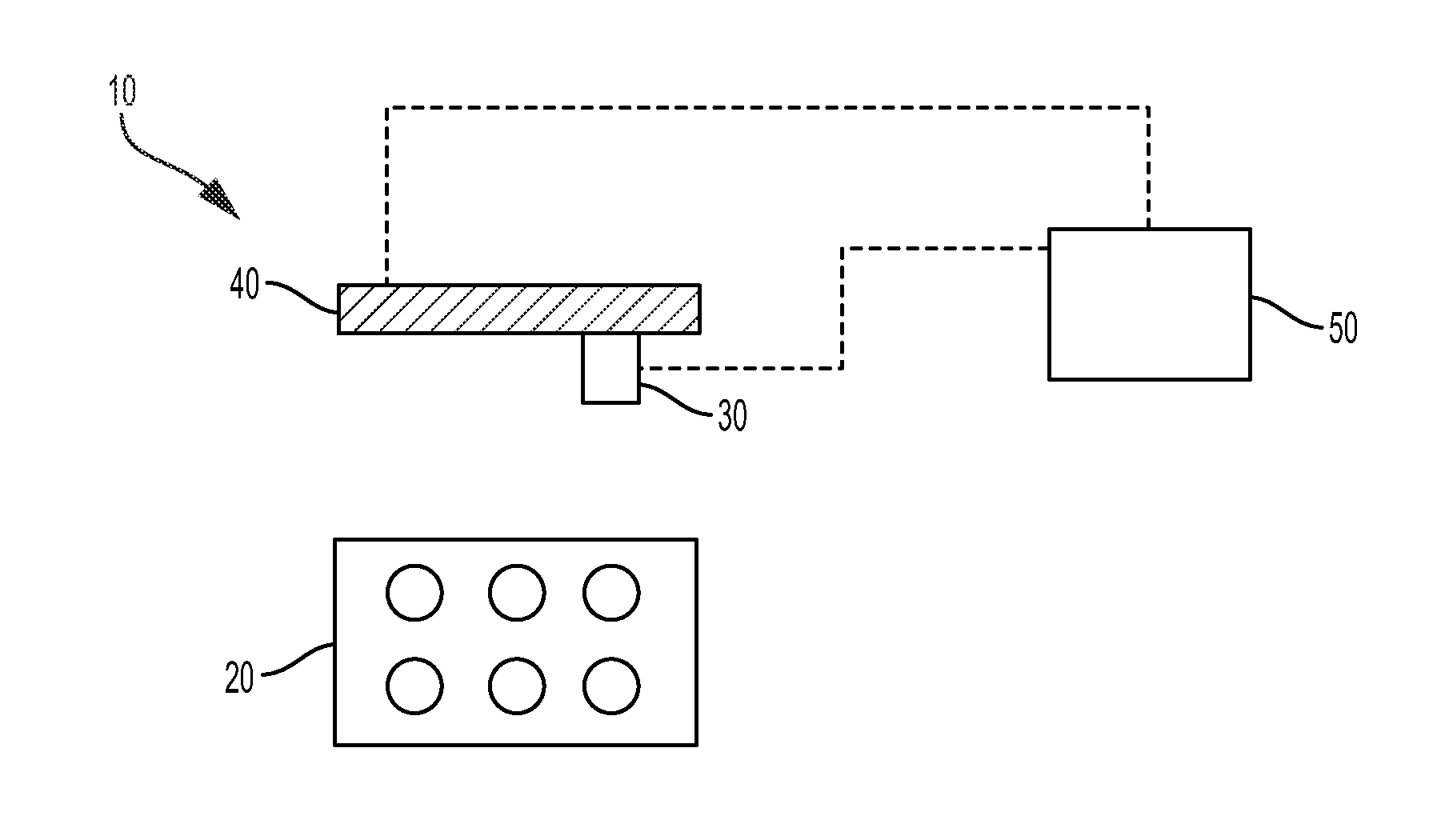
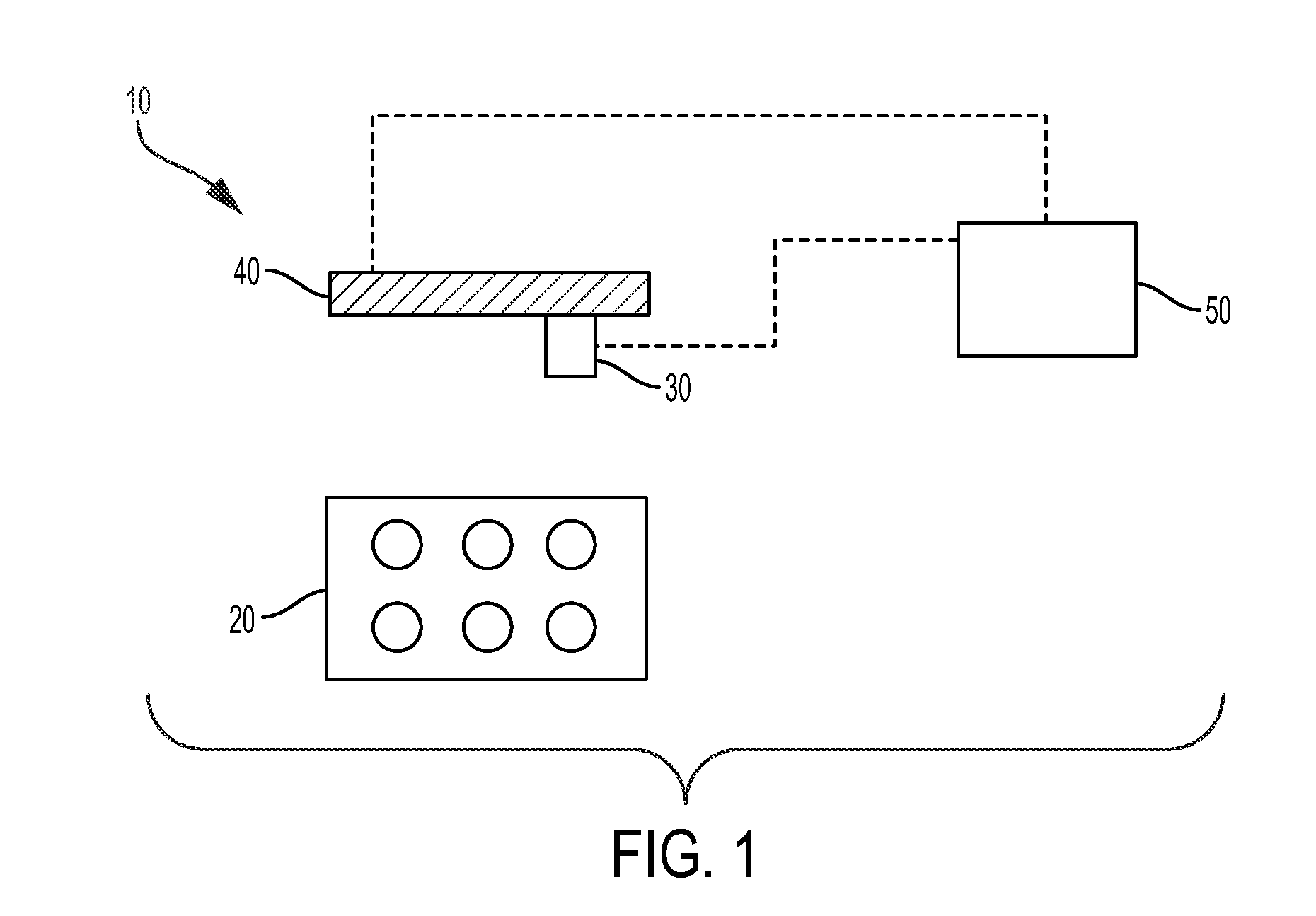
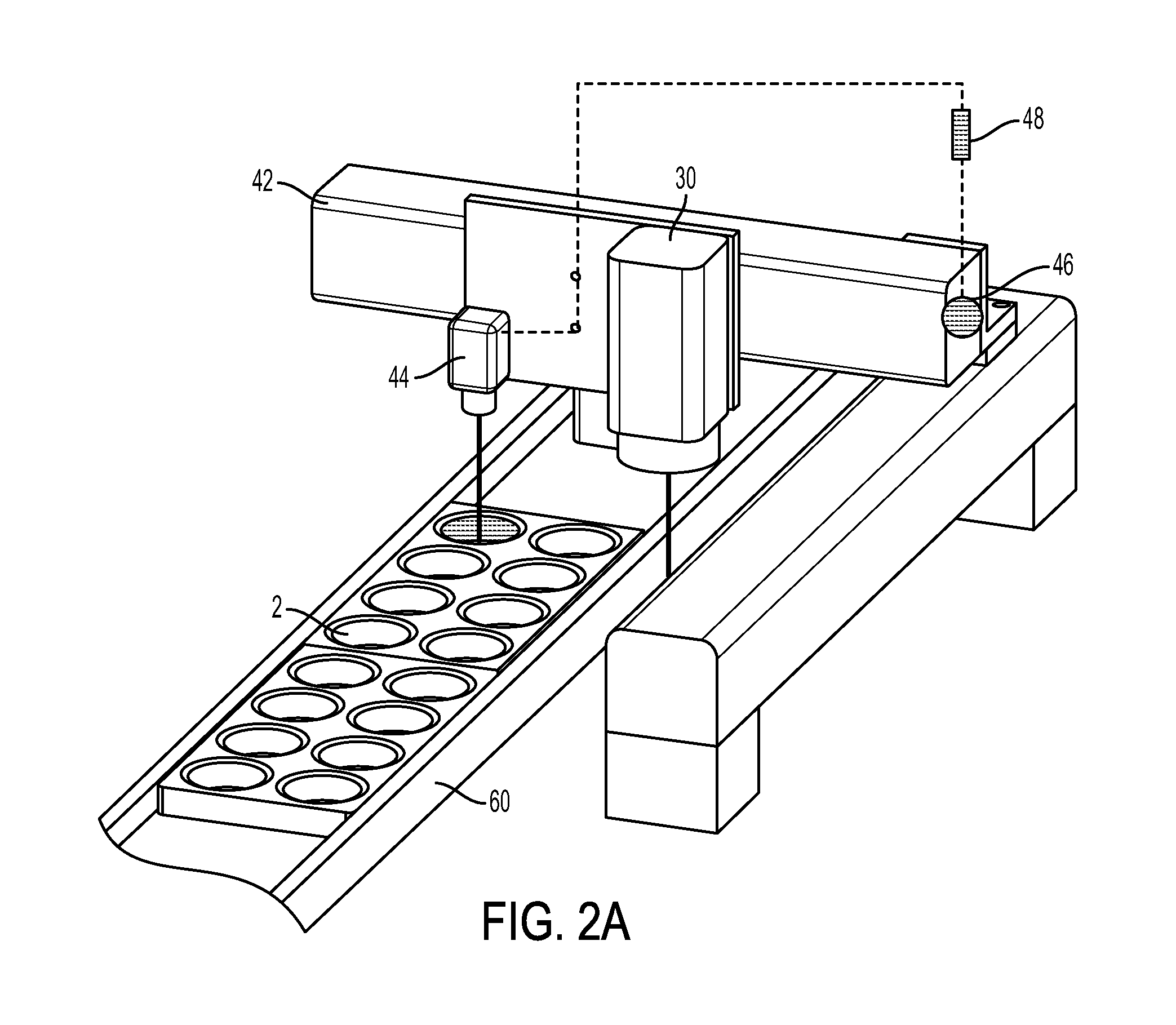
[0022]Apparatuses that allow for in-line analysis of ophthalmic devices are provided. An ophthalmic device may be a contact lens, intraocular lens, ocular insert, or a mold for making any of the foregoing. Using interferometry equipment that can acquire all phase data simultaneously, in a minimal amount of time, to enable the analytical equipment to m...
PUM
 Abstract
Description
Claims
Application Information