Fuel injection device for a combustion engine

a technology for fuel injection and combustion engines, which is applied in the direction of machines/engines, liquid fuel feeders, mechanical equipment, etc., can solve the problem that the fuel supply pump must continuously aspira

Inactive Publication Date: 2004-06-03
ROBERT BOSCH GMBH
View PDF7 Cites 15 Cited by
  • Summary
  • Abstract
  • Description
  • Claims
  • Application Information

AI Technical Summary

Problems solved by technology

The disadvantage here is that the fuel-supply pump must continuously aspirat

Method used


Image

  • Fuel injection device for a combustion engine
  • Fuel injection device for a combustion engine
  • Fuel injection device for a combustion engine

Examples


Embodiment Construction

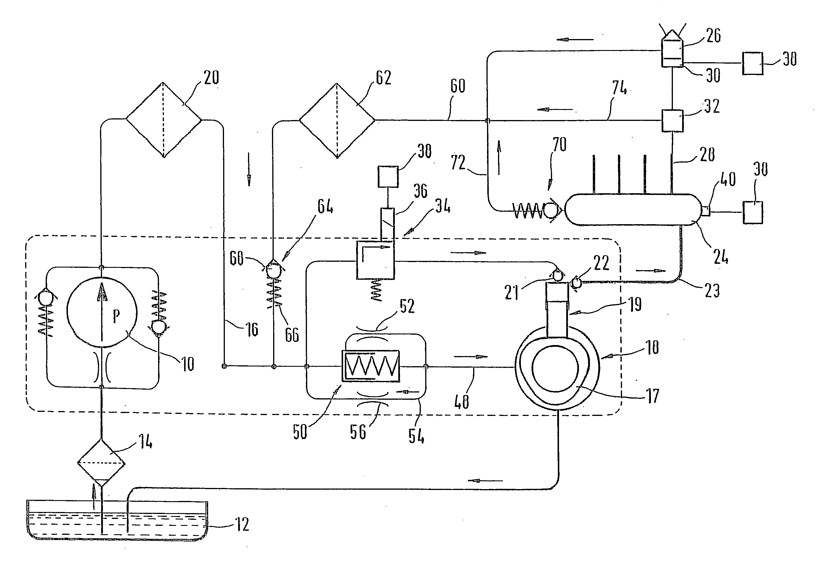
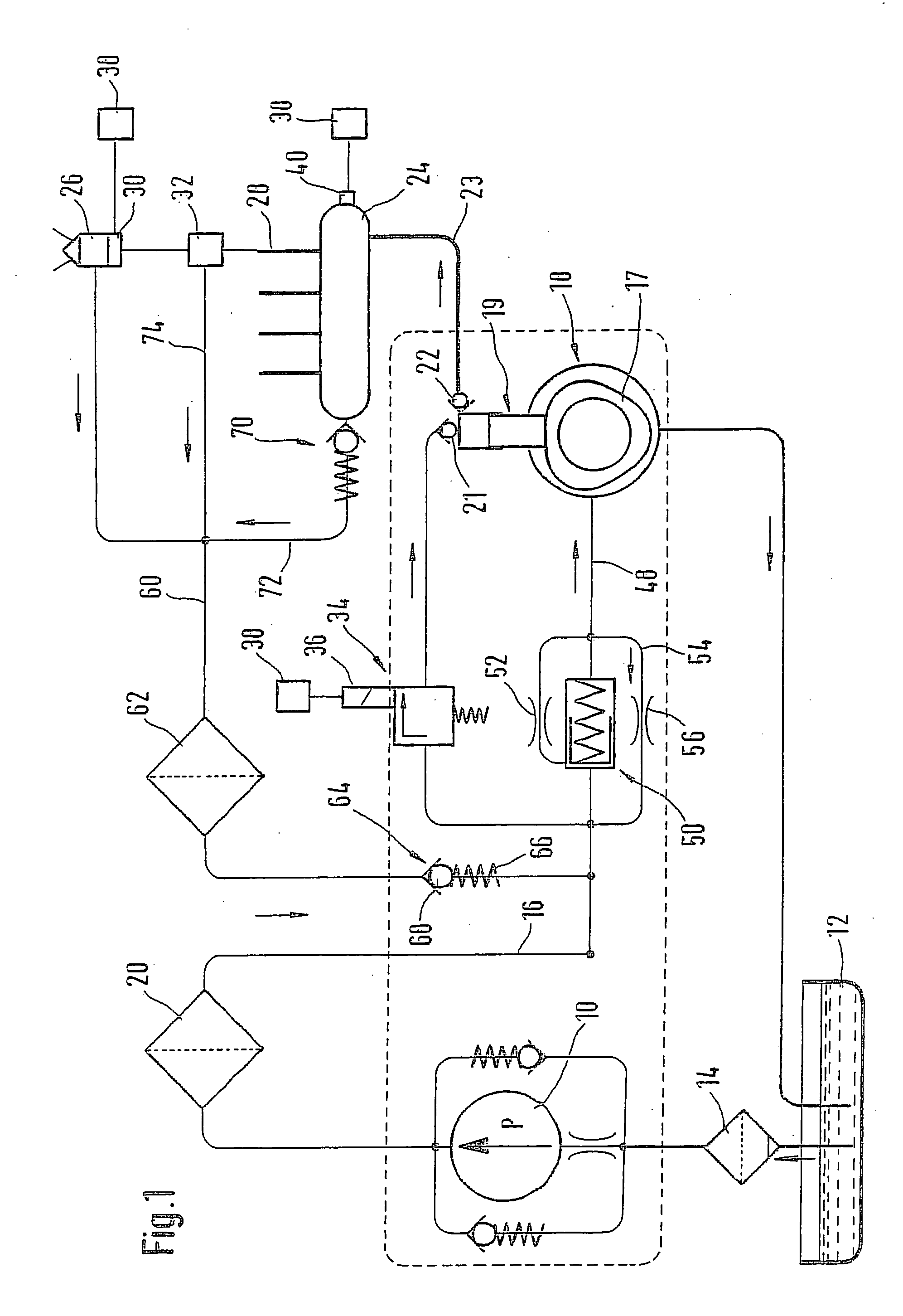
[0008] FIG. 1 shows a fuel injection device for an internal combustion engine, for example of a motor vehicle. The internal combustion engine is preferably an autoignition internal combustion engine and has one or more cylinders. The fuel injection device has a fuel-supply pump 10 that can be disposed inside or outside a fuel tank 12 of the motor vehicle. The fuel-supply pump 10 can have an electric drive motor and draws fuel from the fuel tank 12, for example via a prefilter 14. The fuel-supply pump 10 can also be driven, for example, mechanically by the internal combustion engine or by a high-pressure pump 18 that will be explained below. From the outlet of the fuel-supply pump 10, a connection 16 leads to the high-pressure pump 18. Between the fuel-supply pump 10 and the high-pressure pump 18, the connection 16 is provided with a fuel filter 20 embodied as a fine filter through which the fuel delivered by the fuel-supply pump 10 flows. The fuel filter 20 is designed and dimension...


PUM


Abstract

The fuel injection device has a fuel-supply pump (10) that delivers fuel from a fuel tank (12) to a high-pressure pump (18), wherein the high-pressure pump (18) delivers fuel to a reservoir (24), which is connected to at least one injector (26) that injects fuel into the internal combustion engine. A fuel filter (20) is disposed between the fuel-supply pump (10) and the high-pressure pump (18), wherein a return (60) for fuel from the at least one injector (26) and/or from the reservoir (24) to a low-pressure region is provided. The return (60) is provided with an additional fuel filter (62) and downstream of the fuel filter (20), the return (60) feeds into the connection (16) between the fuel-supply pump (10) and the high-pressure pump (18).

Description

PRIOR ART[0001] The invention is based on a fuel injection device for an internal combustion engine as generically defined by the preamble to claim 1.[0002] A fuel injection device of this kind is known from the literature, for example Dieselmotor-Management, Verlag Vieweg, 2.sup.nd edition 1998, p. 262. This fuel injection device has a fuel-supply pump that delivers fuel from a fuel tank to a high-pressure pump. The high-pressure pump delivers fuel into a reservoir, which is connected to injectors that inject fuel into the internal combustion engine. A fuel filter is disposed between the fuel-supply pump and the high-pressure pump. A return is provided for uninjected fuel, leading from the injectors to a low-pressure region that is constituted by the fuel tank. The disadvantage here is that the fuel-supply pump must continuously aspirate a large quantity of fuel, part of which must be returned to the fuel tank. The fuel-supply pump and the fuel filter must therefore be dimensioned ...

Claims


Application Information

Patent Timeline
IPC IPC(8): F02M37/00F02M37/04F02M37/22F02M53/00F02M55/00F02M55/02F02M63/00F02M63/02
CPCF02M53/00F02M55/002F02M2200/315F02M63/0225F02M63/0001F02M55/02F02M63/00F02M63/02
Inventor GEYER, GERHARD
Owner ROBERT BOSCH GMBH
Why Eureka
Try Eureka