Enclosed shaft system for marine propulsion

a technology of enclosed shafts and marine propulsion, applied in the direction of marine propulsion, vessel construction, propulsive elements, etc., to achieve the effects of preventing premature corrosion, preventing marine growth, and reducing the exposure of the drive shaft to the environmen

Active Publication Date: 2008-09-04
STOLPER PETER R
View PDF12 Cites 9 Cited by
  • Summary
  • Abstract
  • Description
  • Claims
  • Application Information

AI Technical Summary

Benefits of technology

[0024]Disclosed is an enclosed, oil filled shaft and thrust bearing assembly in a marine vessel. The enclosure eliminates the exposure of a drive shaft to the environment. In a conventional marine vessel drive shaft installation, the drive shaft is exposed to the saltwater thereby requiring sacrificial zincs to prevent premature corrosion and paint to prevent marine growth. Degradation of the zinc, as well as the paint, together with various environmental pressures can result in vibrations. The thrust bearing assembly allows the thrust to be directed to the shafts mounting system rather than through

Problems solved by technology

Degradation of the zinc, as well as the paint, together wit

Method used


Image

  • Enclosed shaft system for marine propulsion
  • Enclosed shaft system for marine propulsion
  • Enclosed shaft system for marine propulsion

Examples


Embodiment Construction

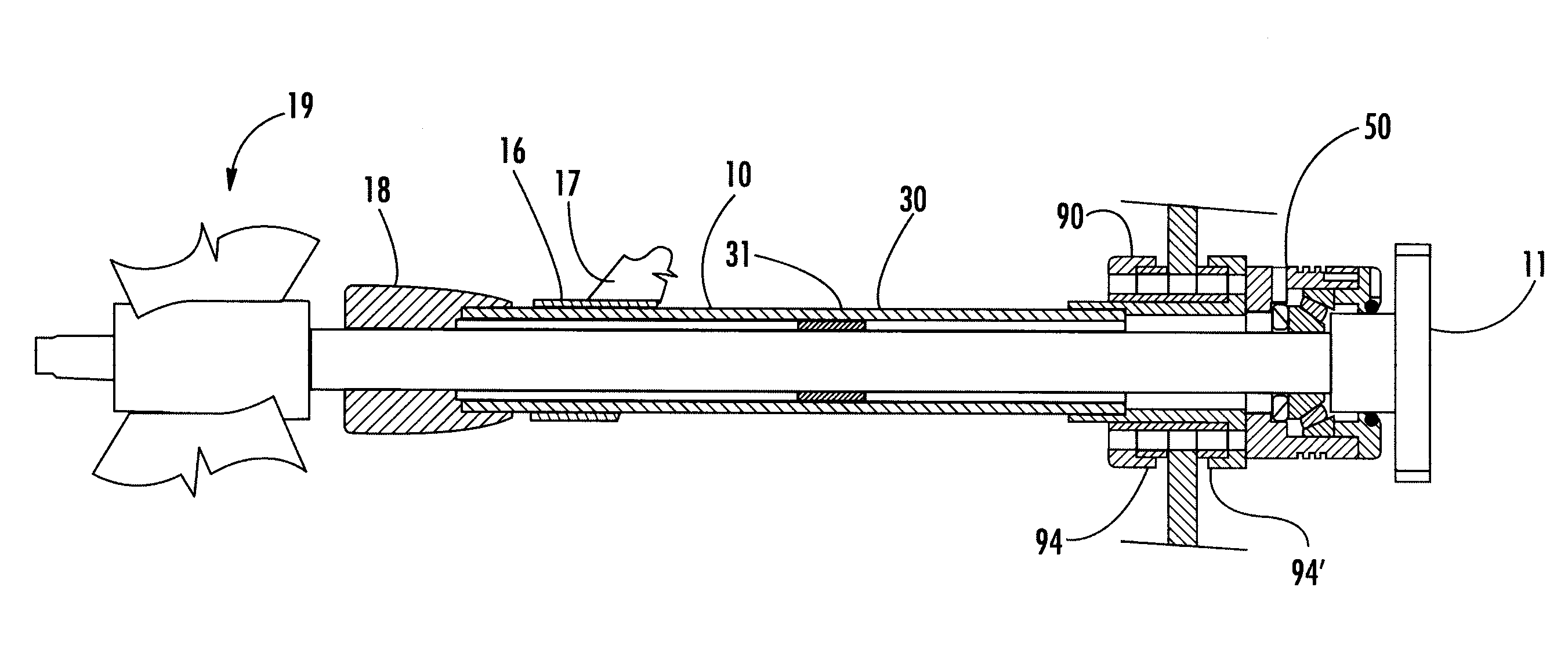
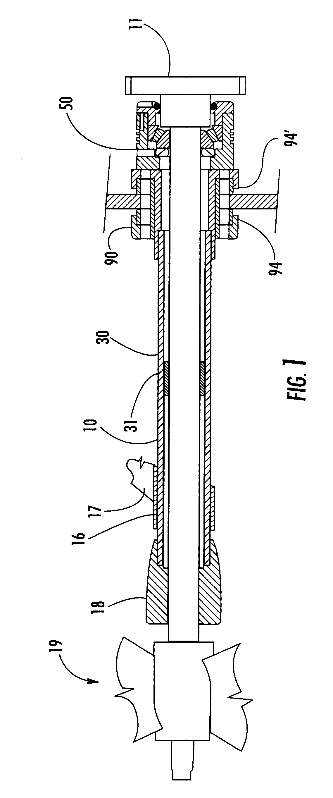
[0044]Enclosed Shaft System. Referring first to FIG. 1, the outer casing or enclosure 30 of the enclosed shaft system is shown. In the preferred embodiment, it is constructed of stainless steel pipe of ASTM grade 316 or 304. The pipe size for each casing is carefully selected so that the mounting strut 17 used by the original equipment manufacturer (OEM) can, with little modifications; accommodate the casing once the original bearing (not shown) has been removed from the strut barrel 16.

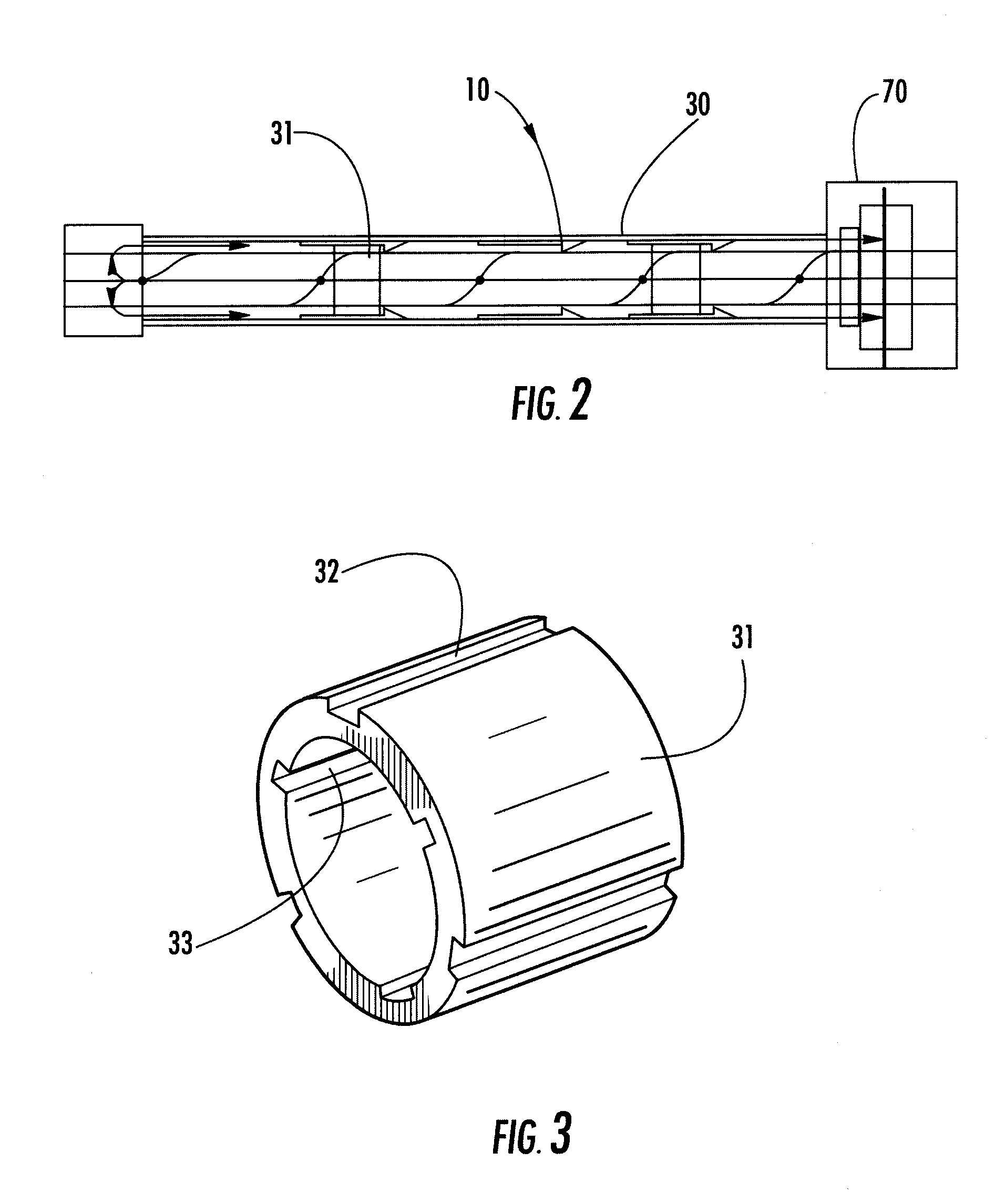
[0045]Journal Bearing or Bearings. Within the casing 30 there are one or more bronze journal bearings 31. These are fully hydrodynamic, i.e. they are fully submerged in fluid lubricant. The rotation of the shaft 10 pulls lubricant in the direction of rotation towards the center of the journal, and builds a dynamically generated pressure within the journal bearing 31, precluding metal-to-metal contact. In the preferred embodiment with proper tolerances, these bearings develop approximately 10 PSI at n...


PUM


Abstract

The system is an enclosed, oil filled, shaft and thrust bearing assembly which includes an oil pump to circulate the oil throughout the system. The thrust bearing assembly allows the thrust to be directed to the shafts mounting system rather than through the vessels main propulsion engines and isolators thereby reducing vibration and noise emissions. In addition the elimination of thrust loading transmitted directly to the propulsion engines reduces wear and tear on the engine mounts, isolators and engine support structures. The non rotating casing of the shaft assembly allows clean water to flow to the propeller which allows more delivered horsepower to be used by the propeller.

Description

CROSS-REFERENCE TO RELATED APPLICATIONS[0001]This application is based and claims the filing date of Provisional Patent Application No. 60 / 828,379 filed Oct. 5, 2006 the contents of which are incorporated herein by reference.FIELD OF THE INVENTION[0002]The invention relates generally to power boats, specifically to the delivery of power from the engine of a power boat to a propeller, and back to the boat itself to effect forward or reverse motion in water. More specifically, my invention relates to a reliable and economical form of self-contained, enclosed drive shaft and associated components, suitable for installation on small boats.BACKGROUND OF THE INVENTION[0003]The enclosed shaft system of the present invention provides in a unified structure, including a unique arrangement of bearings and an impeller-distributor to create continuous circulation of fluid lubricant among all bearing surfaces, wherein one or more journal bearings stabilize shaft movement and permit the flow of l...

Claims


Application Information

Patent Timeline
IPC IPC(8): B63H20/14
CPCB63H23/321B63H23/36
Inventor STOLPER, PETER R.
Owner STOLPER PETER R
Why Eureka
Try Eureka