
Compact disk (CD) storage case and method for storing a CD

a technology of compact disk and storage case, which is applied in the direction of transportation and packaging, instruments, packaged goods types, etc., can solve the problems of exposing the disk retained within to a greater potential for damage, the need for disposal, and the user's re-apply difficulty

Inactive Publication Date: 2004-06-10
FORD PHILIP +3
View PDF3 Cites 3 Cited by
  • Summary
  • Abstract
  • Description
  • Claims
  • Application Information

AI Technical Summary

Benefits of technology

[0014] These and other objects of this invention are achieved by providing a two-piece disk container or case having as one of the two pieces a sliding lid for retaining the disk therein. It is contemplated that the disk container may retain any sort of mass storage disk including, but not limited to, CDs, DVDs, computer memory disks and the like. The two pieces of the case may be formed of any suitable material including, but not limited to, relatively pliable viscoelastic materials such as polypropylene and polyethylene. Forming the case of such a material minimizes structural failure of the case under high-stress conditions (such as dropping) and further protects, to a degree, the disk within under such conditions.
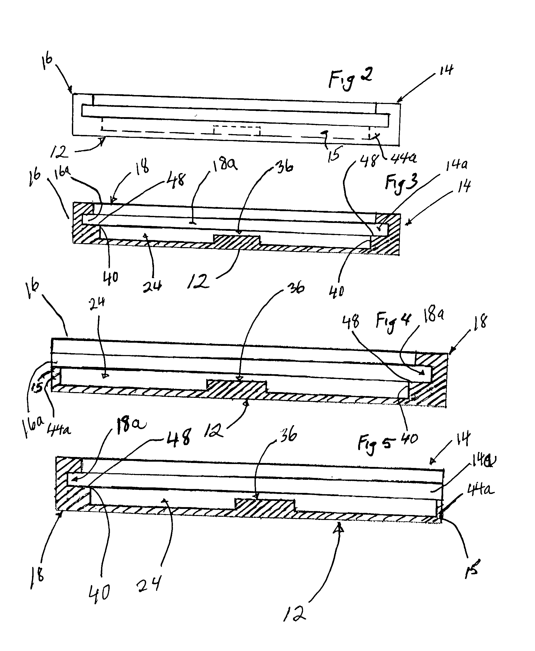
[0016] Each of the sidewalls and the single endwall include slide channels at corresponding opposing sides incorporated as part of each sidewall. The slide channels are designed to provide a releasable interference fit with the outer edges of the lid. The use of slide channels rather than hinges enables continual use of the lid and the base. The arrangement of the lid and capturing slide channels also limits the opportunity of the lid to become irreparably dislodged from the base under a wide array of actual-use conditions. The inside perimeter of the lid preferably, and the inside perimeter of the base may, have one or more material-retention tabs for removably capturing in place on the transparent faces thereof any graphic or informational material to be included with the disk. The sidewalls and a front endwall of the lid are designed to couple the lid to the base when the case is closed by way of an interference fit, locking tabs, or other suitable means.

Problems solved by technology

Unfortunately, the previous hinged designs often result in irreparable damage through normal use to one or more parts or pieces of the hinge mechanisms causing the need for disposal.
Once the lid has been removed, it can be difficult for the user to re-apply it and, in some instances, may not attempt to, thereby exposing the disk retained within to a greater potential for damage.
Unfortunately, this transparent material is quite brittle and can either crack under a variety of stress conditions--such as by banging against a fixed surface, or by being dropped.
In addition, even if the brittle case does not fail, its rigidity can translate impact conditions directly to the disk contained therein, thereby causing its failure.
There exists a concern with the process of opening a hinged lid too abruptly causing damage beyond repair thus causing the need for discarding and replacement with previous inventions and designs.
Apart from that, it is not particularly desirable to have a variety of disk containers as it makes it much more difficult to establish standardized disk packaging equipment and processes.
Also, what is needed is a disk container having a lid-and-base arrangement that limits the opportunity for damage of those components under expected use conditions.
The arrangement of the lid and capturing slide channels also limits the opportunity of the lid to become irreparably dislodged from the base under a wide array of actual-use conditions.

Method used


Image

  • Compact disk (CD) storage case and method for storing a CD
  • Compact disk (CD) storage case and method for storing a CD
  • Compact disk (CD) storage case and method for storing a CD

Examples


Embodiment Construction

[0033] In the description herein, numerous specific details are provided, such as examples of components and / or methods, to provide a thorough understanding of embodiments of the present invention. One skilled in the relevant art will recognize, however, that an embodiment of the invention can be practiced without one or more of the specific details, or with other apparatus, systems, assemblies, methods, components, materials, parts, and / or the like. In other instances, well-known structures, materials, or operations are not specifically shown or described in detail to avoid obscuring aspects of embodiments of the present invention.

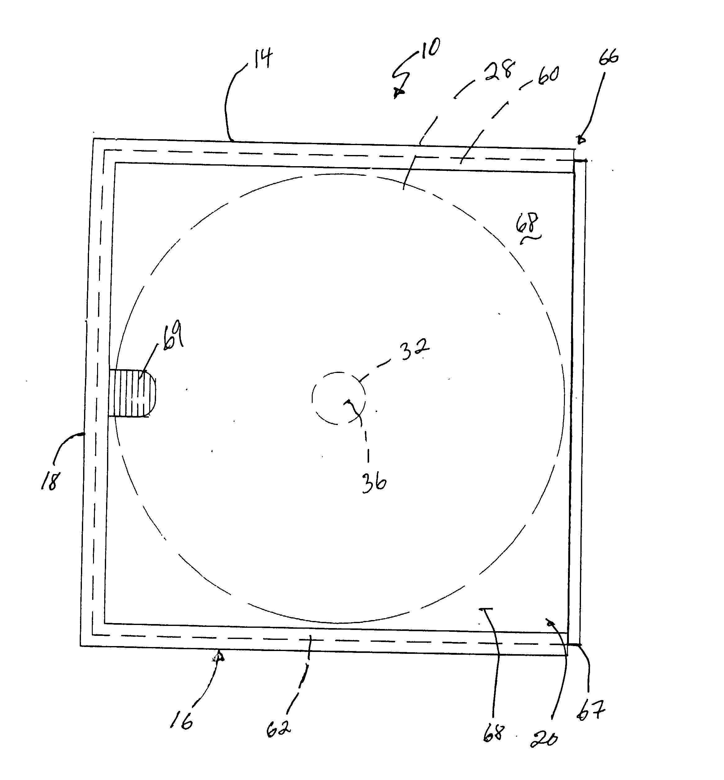
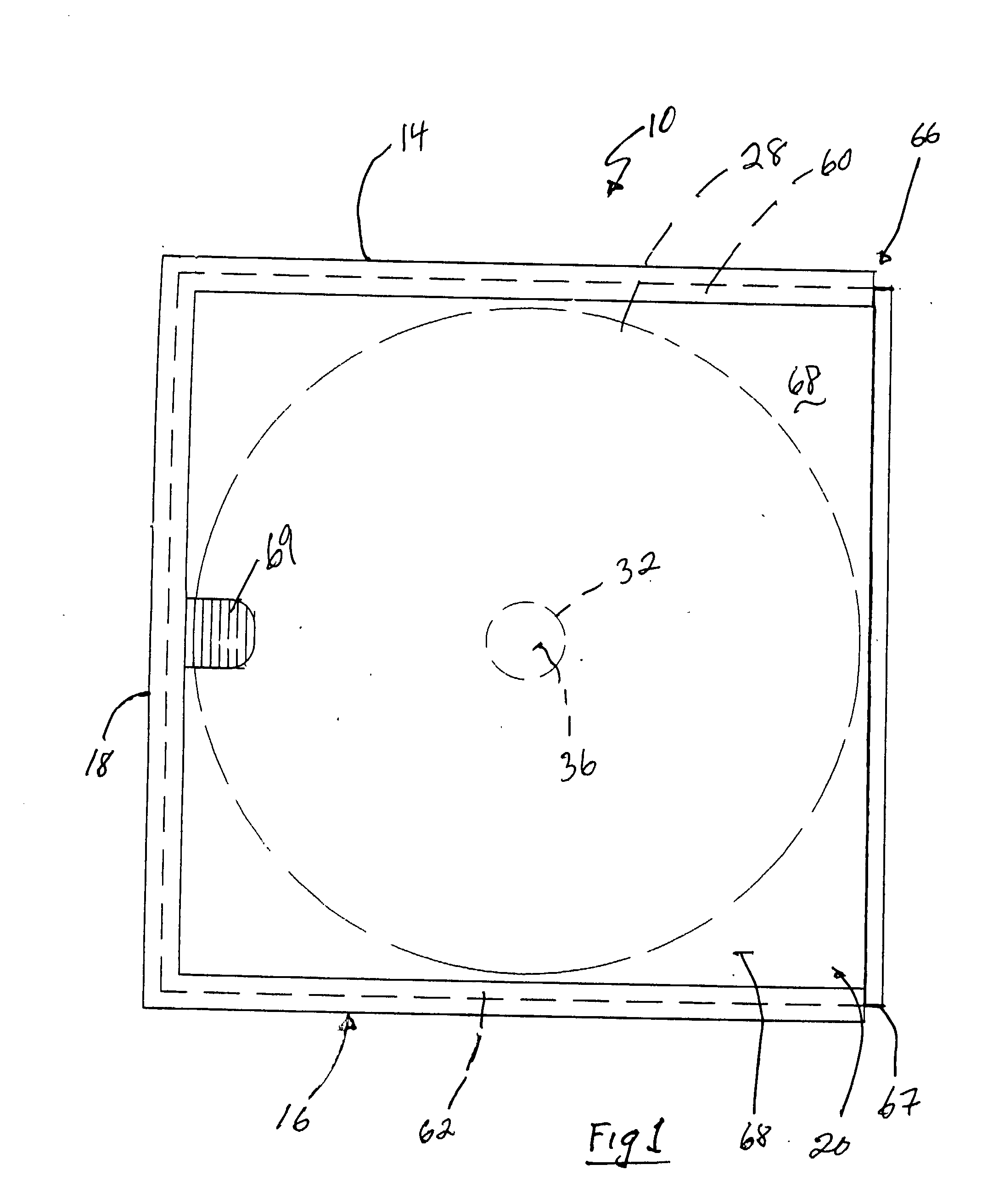
[0034] Referring now to the drawings wherein similar parts of the invention are identified by like reference numbers, there is seen a disk storage container, generally illustrated as 10. The storage container 10 comprises a base, generally illustrated as 12, a pair of side walls, generally illustrated respectively as 14 and 16 and secured to the base 12, ...


PUM

PropertyMeasurementUnit
structureaaaaaaaaaa
perimeteraaaaaaaaaa
transparentaaaaaaaaaa

Abstract

A method for storing a disk comprising providing a disk having a disk opening, providing a disk storage container having a base with a disk recess and a hub generally concentrically disposed in the disk recess, and disengaging an end side of a lid from a rear channel of an upright rear wall attached to said base. The method for storing additionally comprises sliding opposed sides of the lid in side channels of opposed upright side walls attached to the base and to the upright rear wall, passing the hub of the disk recess through the disk opening of the disk, and resting the disk on a bottom of the disk recess for storing the disk. A disk storage assembly having a base including a structure defining a generally circular recess having a concentrically disposed hub, an upright rear wall attached to the base, and a pair of upright side walls attached to the base and to the upright rear wall with each side wall having a structure defining a side channel that communicates with the rear channel and is generally collimated therewith. A lid is slidably disposed in the side channels.

Description

[0001] 1. Field of the Invention[0002] Embodiments of the present invention relate generally to a disk (e.g., CDs, digital-video disks(DVDs) and other disk storage devices) storage case. More particularly, embodiments of the present invention provide a non-hinged compact disk (CD) storage case and method for storing a CD. More particularly further, embodiments of the present invention provide a method for storing a CD and a compact disk storage case having a sliding lid that is neither hinged nor otherwise pivotally coupled to the base.[0003] 2. Description of the Background Art[0004] The ongoing success of optically readable mass storage media, such as CDs, computer Read Only Memory (ROM) disks, and, more recently, DVDs, has generated the need for relatively inexpensive cases for safely storing such disks therein, the most popular standard case for CDs is the jewel case, a transparent hinged three-part structure designed to retain the disk within. The jewel case has essentially bec...

Claims


Application Information

Patent Timeline
Patent Type & Authority Applications(United States)
IPC IPC(8): G11B33/04
CPCG11B33/045G11B33/0427
Inventor FORD, PHILIPTHOMAS, ALLEN F.GOUGH, MARKFLINN, ERICK
Owner FORD PHILIP
Learn More