Auger airlock assembly and end dump housing

a technology of airlock and end dump, which is applied in the direction of conveyors, packaging, loading/unloading, etc., can solve the problems of weakened vacuum and suction effect, two related problems in the conventional loader auger airlock or housing, and increase the cost of operation, so as to preserve the integrity of the overall negative pressure system, improve the efficiency, and maintain the negative pressure situation

Inactive Publication Date: 2007-07-19
AG GROWTH IND PARTNERSHIP
View PDF8 Cites 10 Cited by
  • Summary
  • Abstract
  • Description
  • Claims
  • Application Information

AI Technical Summary

Benefits of technology

[0015]The advantage of the present invention is that it provides an improved high efficiency auger airlock assembly and end dump housing which can maintain the vacuum suction created by the negative pressure in the loader and auger assembly.
[0016]A further advantage of the present invention is that it provides an improved high efficiency auger airlock assembly and end dump housing which limits the opportunity for outside air to enter the discharge port from the sides of the port upon the discharge of materials, thus preserving the integrity of the overall negative pressure system and maintaining the negative pressure situation in the loader and the auger assembly.
[0017]Yet another advantage of the present invention is that it provides an improved auger airlock assembly and end dump housing which restricts the direction in which materials are discharged downwardly from the end of the discharge port.

Problems solved by technology

The use of auger airlocks or housings is not new in the industry.
However, two related problems have arisen in conventional loader auger airlocks or housings.
The first is that materials exiting from the outlet through the airlock doors generally allow, once the airlock door is opened for the removal of materials, outside air to enter into the barrel or tube, which weakens the vacuum and suction effect.
The second further problem stems from the possibility, once outside air has entered into the barrel or tube of the auger assembly, is that material being transported by the auger to be exited can be blown back down the auger assembly, resulting in what is commonly known as “blowback”.
When this occurs, it is not uncommon for almost all of the vacuum effect created by the airlock to be lost.

Method used


Image

  • Auger airlock assembly and end dump housing
  • Auger airlock assembly and end dump housing
  • Auger airlock assembly and end dump housing

Examples


Embodiment Construction

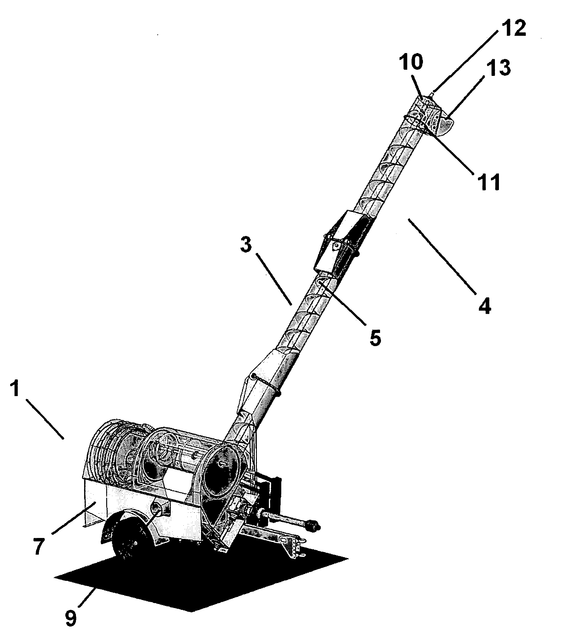
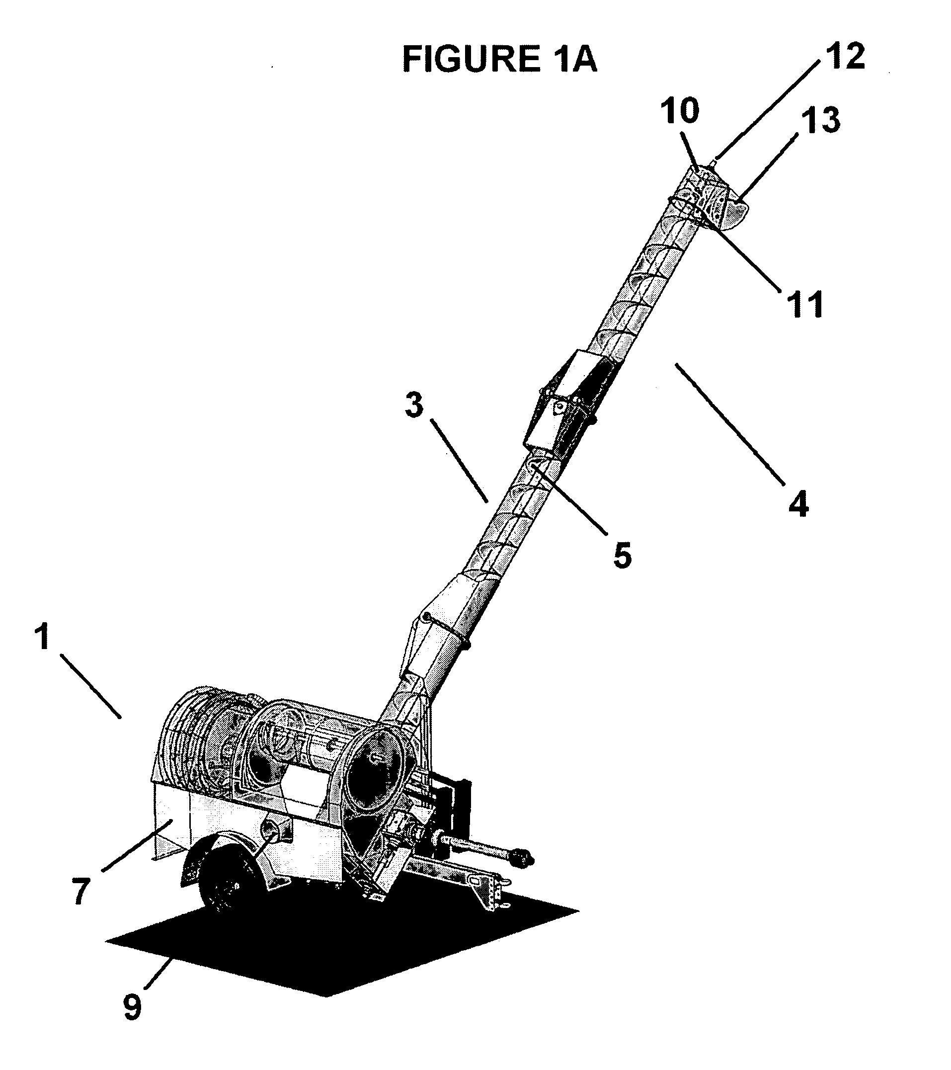
[0025]FIG. 1A broadly illustrates a conventional example of a bulk loader (1) utilizing an auger airlock assembly and end dump housing in accordance with the present invention. As is known in the art, such bulk loaders utilize a blower or fan to create a source of negative pressure for forming a suction air stream that draws particulate or granular materials through a hose into the loader for subsequent transfer, via an auger assembly, to a location remote of the loader. The bulk loader shown in FIG. 1A provides an inlet (9) in a sidewall of the body (7) which is adapted to be connected with an intake hose or conduit (not shown) so that particulate or granular materials may be drawn, by suction, through the hose and passed into the interior of the bulk loader, for transferral to the auger airlock assembly of the present invention (indicated generally as “4”), which, in a preferred embodiment, includes an elongated material conveying tube or barrel (3), and an elongated, axially rota...


PUM


Abstract

An auger airlock assembly and end dump housing having a spring loaded bottom for use in a bulk loader which utilizes a source of negative pressure to create a suction air stream that draws particulate materials into the loader for transfer, via the auger assembly, to a location remote of the loader. Materials exiting the auger assembly accumulate within the housing to a point wherein, once the accumulated material has acquired a certain weight, the bottom of the housing is forced open to permit discharge of the material, and, once the material is removed, and is not present in enough quantity to maintain the bottom of the housing to remain open, the spring loaded connection biases the bottom back into a position sealably closing the housing. The bottom of the housing may also be opened by the auger feeding more material into an already full housing, whereby the material is compressed so as to force the door open. Side portions of the housing limit the opportunity for outside air to enter the airlock assembly during the discharge of materials, maintaining the vacuum suction created by the negative pressure in the auger assembly.

Description

FIELD OF THE INVENTION[0001]This invention relates to an auger airlock assembly and end dump housing for bulk loaders, and, more particularly, to an auger airlock assembly and end dump housing for use in a bulk loader which utilizes a source of negative pressure to create a suction air stream that draws particulate materials into the loader for removal by an auger to a location remote from the loader.DESCRIPTION OF THE PRIOR ART[0002]Generally speaking, prior auger assemblies include an elongated barrel or tube presenting a material inlet and a material outlet spaced from the inlet, with an elongated, axially rotatable, material-conveying auger screw positioned within the tube. Auger assemblies are often used for conveying materials such as granular agricultural products along a desired path of travel, for example, from the outlet of a cyclone separator to a collection hopper. Further, such machines may also utilize a single stage fan or blower to create suction for the vacuum picku...

Claims


Application Information

Patent Timeline
Patent Type & Authority Applications(United States)
IPC IPC(8): B65G33/00
CPCB65G33/14B65G69/181B65G33/24B65G33/22
Inventor NOBLE, MAXREMPEL, FRANK
Owner AG GROWTH IND PARTNERSHIP
Why Eureka
Try Eureka