
Extensometer with long base, tensioned optical fibre and bragg rating, and manufacturing process for this extensometer

Inactive Publication Date: 2004-06-17
COMMISSARIAT A LENERGIE ATOMIQUE ET AUX ENERGIES ALTERNATIVES
View PDF6 Cites 44 Cited by
  • Summary
  • Abstract
  • Description
  • Claims
  • Application Information

AI Technical Summary

Benefits of technology

The invention is about an optical fiber-based extensometer that uses Bragg gratings to measure deformations and cracks in structures, such as bridges and buildings. The advantages of this invention include its insensitive to electromagnetic disturbances, stable with time, and able to make long-term monitoring measurements. The invention can be used in various domains, such as civil engineering, public works, and geotechnical engineering. The Bragg gratings are placed on optical fibers and can be embedded in concrete or other materials to monitor their health.

Problems solved by technology

There is a disadvantage with known extensometers: due to the structure of these extensometers, their base length cannot exceed more than about a meter.

Method used


Image

  • Extensometer with long base, tensioned optical fibre and bragg rating, and manufacturing process for this extensometer
  • Extensometer with long base, tensioned optical fibre and bragg rating, and manufacturing process for this extensometer
  • Extensometer with long base, tensioned optical fibre and bragg rating, and manufacturing process for this extensometer

Examples


Embodiment Construction

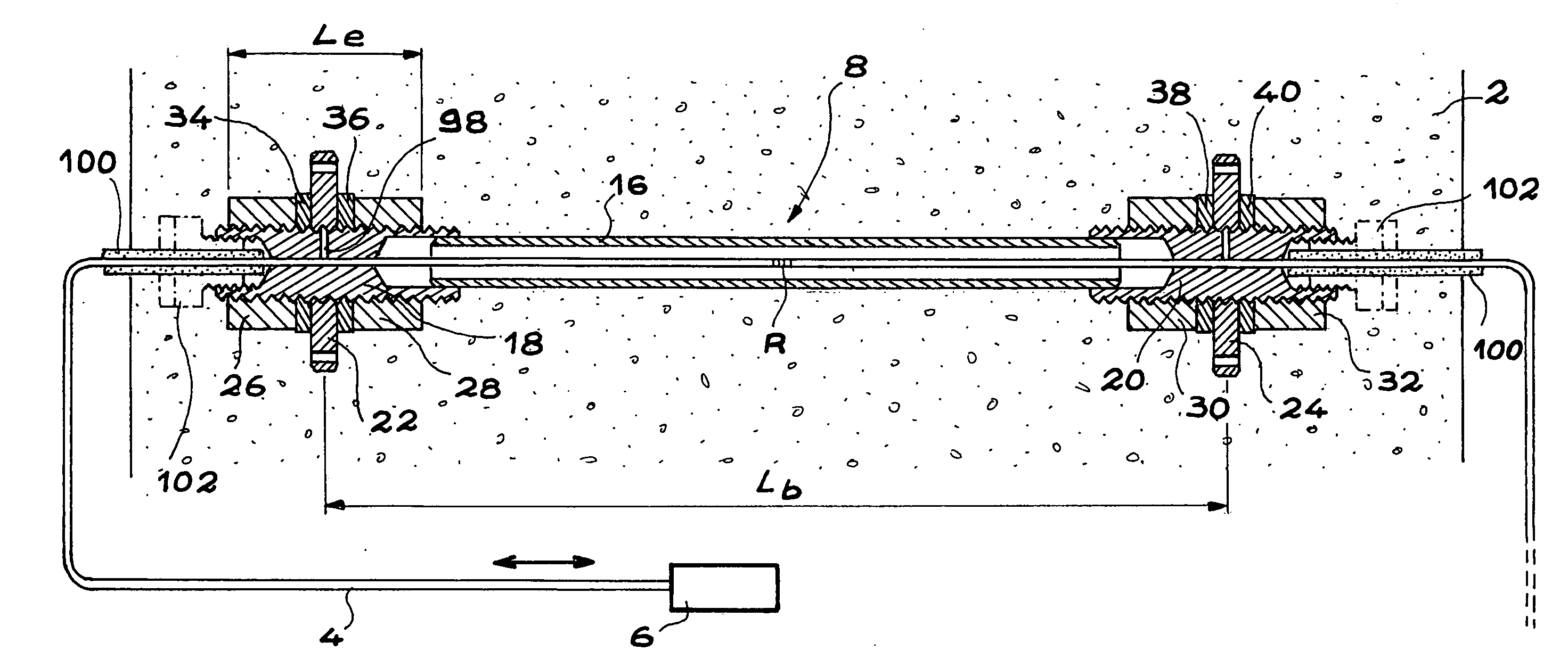
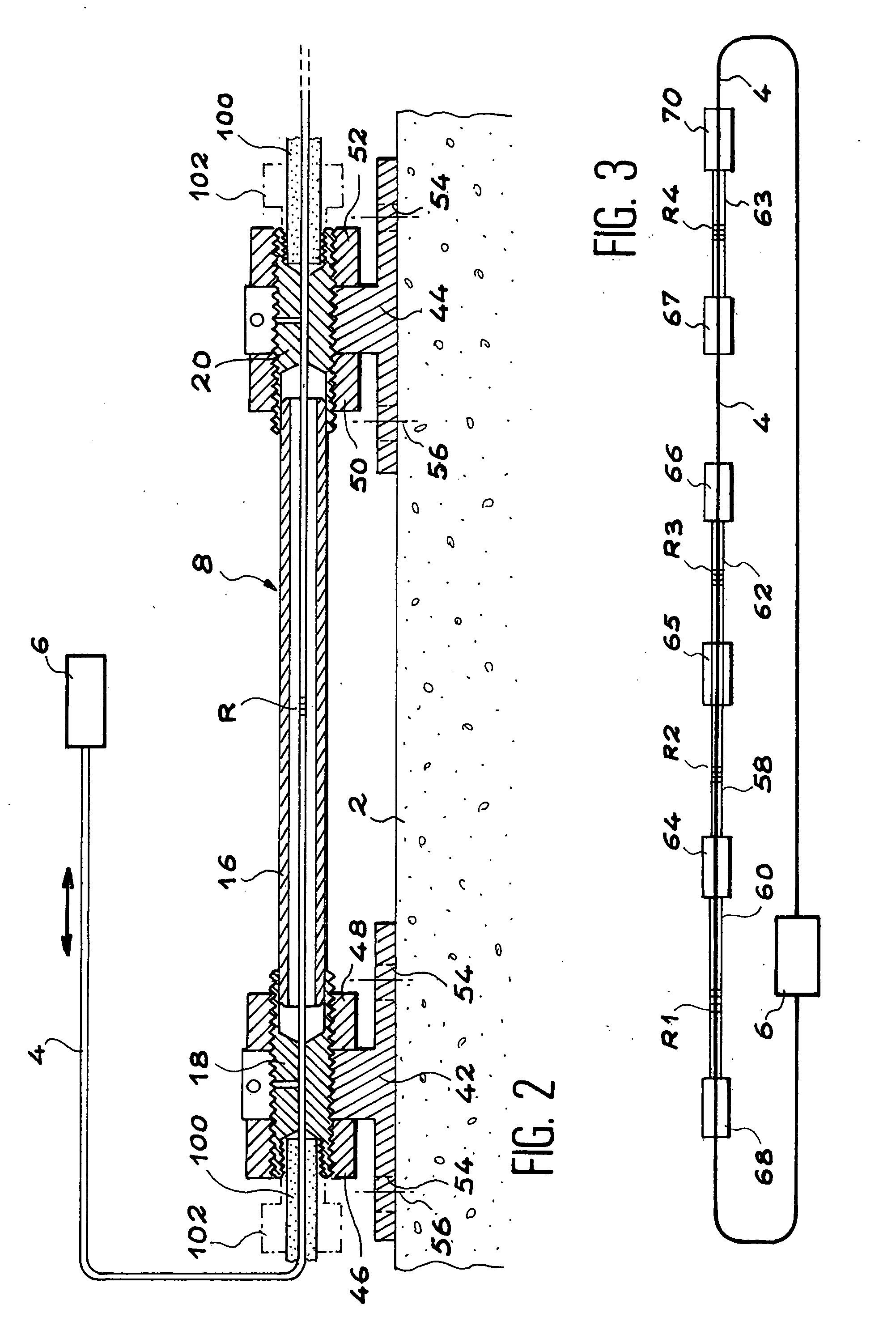
[0053] Extensometers according to the invention that are diagrammatically shown in longitudinal cross section in FIGS. 1, 2 and 3, will be used to measure deformations (contractions or expansions) of a host material which in these examples is a concrete structure.

[0054] Each of these extensometers comprises an optical fiber containing at least one Bragg grating, and the fiber containing the Bragg grating is pretensioned with an elongation greater than the maximum allowable compression, so that elongation and contraction deformations can be measured.

[0055] Thus for concrete, the compression range is of the order of 2500 .mu. deformation (0.2%). It can be seen that it is quite possible to pretension the fiber to more than this value (for example 0.5%).

[0056] FIGS. 1 and 2 show the concrete part 2 of this structure for which deformations are to be studied using one of these extensometers.

[0057] Each extensometer comprises a preferably single mode optical fiber 4, for example made of si...


PUM

PropertyMeasurementUnit
lengthaaaaaaaaaa
diameteraaaaaaaaaa
temperatureaaaaaaaaaa

Abstract

According to the invention, that relates particularly to monitoring of structures, part of the optical fiber (4) containing a Bragg grating (R) is arranged in a tube (16); this part is tensioned between the two ends of the tube; the ends of this part are fixed to the ends of the tube; this tube will be rigidly fixed to a host material (2).

Description

[0001] This invention relates to an extensometer using an optical fiber that comprises at least one Bragg grating and a process for manufacturing this extensometer.[0002] It is becoming more and more necessary to inspect aging of bridges, and more generally of a large number of civil engineering works and infrastructures. Most such concrete and steel structures are subjected to severe environmental conditions (resulting from the climate, chemical attacks and continuously increasing traffic) that explain their premature aging. Therefore, precise and reliable monitoring means, obviously with a life comparable with the life of the structures being monitored, must be provided for maintenance and public safety reasons.[0003] Several physical parameters related to aging or degradation of these structures are concerned. For example, there are measurements of the pH, chemical composition, deformation and strain in the materials from which these bridges are composed, and detection and monito...

Claims


Application Information

Patent Timeline
Patent Type & Authority Applications(United States)
IPC IPC(8): G01B11/16G01D5/353G01L1/24
CPCG01B11/18G01D5/35316G01M11/085G01L1/246
Inventor DEWYNTERMARTY, VERONIQUEROUGEAULT, STEPHANEFERDINAND, PIERRE
Owner COMMISSARIAT A LENERGIE ATOMIQUE ET AUX ENERGIES ALTERNATIVES
Learn More