Connector packaging tray with supporting standoffs

a technology of connectors and standoffs, applied in the field of connector packaging trays, can solve the problems of cpu socket damage, prone to deformation or warping, and the socket balls are exposed

Inactive Publication Date: 2004-06-17
HON HAI PRECISION IND CO LTD
View PDF8 Cites 5 Cited by
  • Summary
  • Abstract
  • Description
  • Claims
  • Application Information

AI Technical Summary

Problems solved by technology

Thus, during transportation and handling of the CPU sockets 8, the solder balls exposed by the holes 944 are liable to sustain damage and / or break away from their CPU sockets 8.
However, the pick up cap 81 is typically made of thermoplastic material, and is liable to sustain deformation or warping.
When deformation or warping occurs, the inspection of the solder balls for uniform flatness is inaccurate.
This interferes with quality control of the CPU sockets 8.
Thus, in transportation and handling of the CPU sockets, the solder balls are unlikely to sustain damage and / or break away from their CPU sockets.

Method used


Image

  • Connector packaging tray with supporting standoffs
  • Connector packaging tray with supporting standoffs
  • Connector packaging tray with supporting standoffs

Examples


Embodiment Construction

[0015] Reference will now be made to the drawings to describe the present invention in detail.

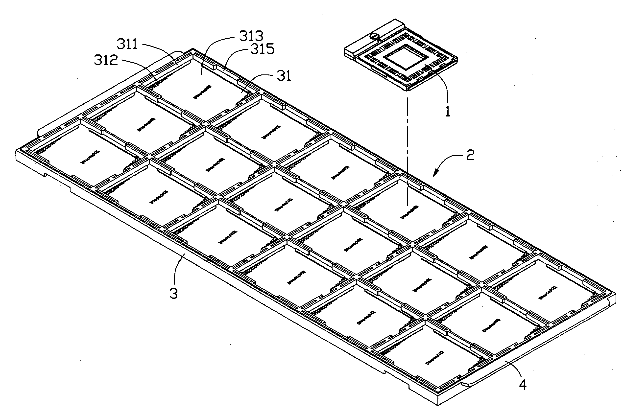
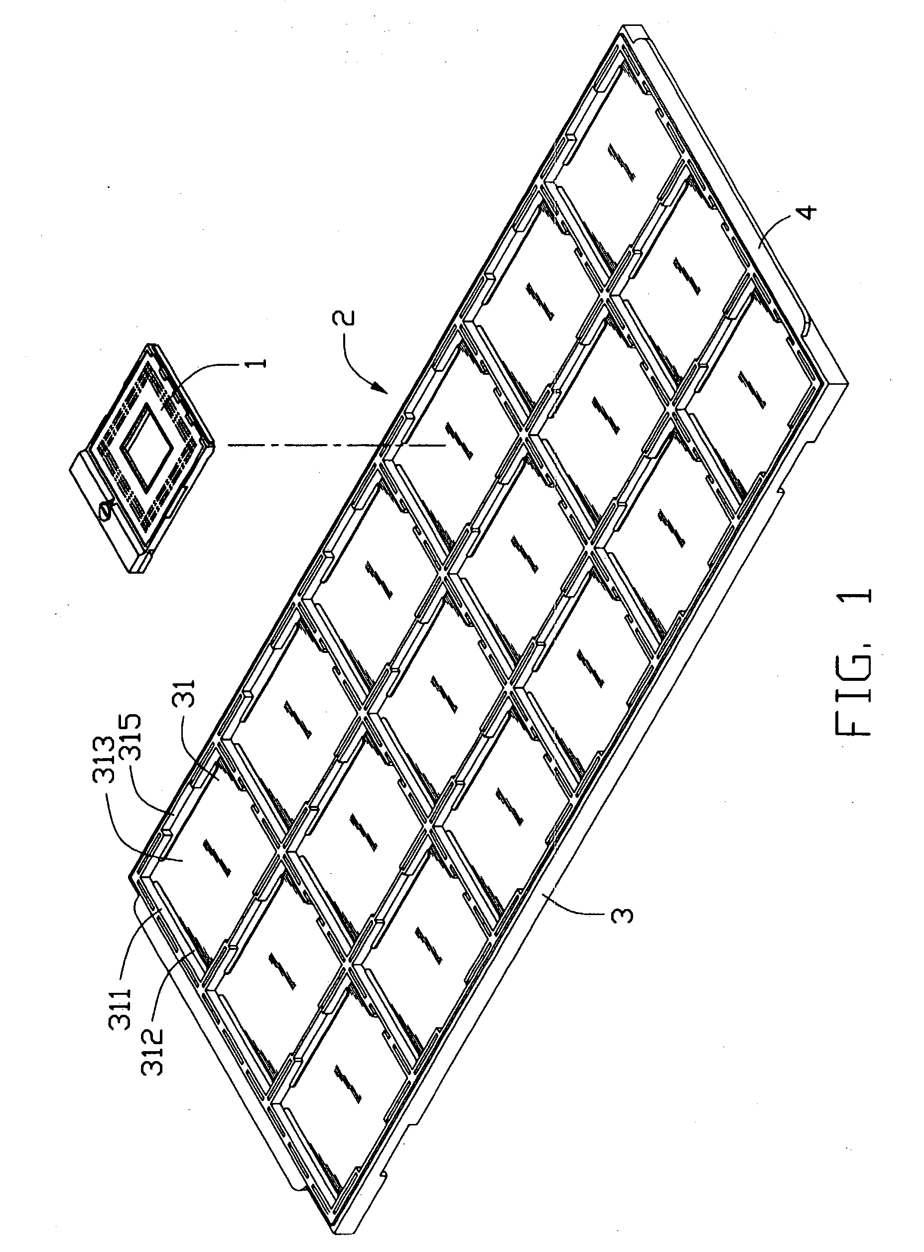
[0016] Referring to FIG. 1, a connector packaging tray 2 is used for receiving several components such as central processing unit (CPU) sockets 1 (only one shown) therein, and providing safe and easy transportation and handling of the CPU sockets 1. Each CPU socket 1 is used for electrically connecting a CPU (not shown) to a circuit substrate such as a printed circuit board (PCB) (not shown) in a personal computer. The CPU socket 1 has a top surface and a bottom surface. A multiplicity of solder balls (not shown) is provided on the bottom surface of the CPU socket 1, the solder balls being adapted for electrically connecting with the PCB by welding.

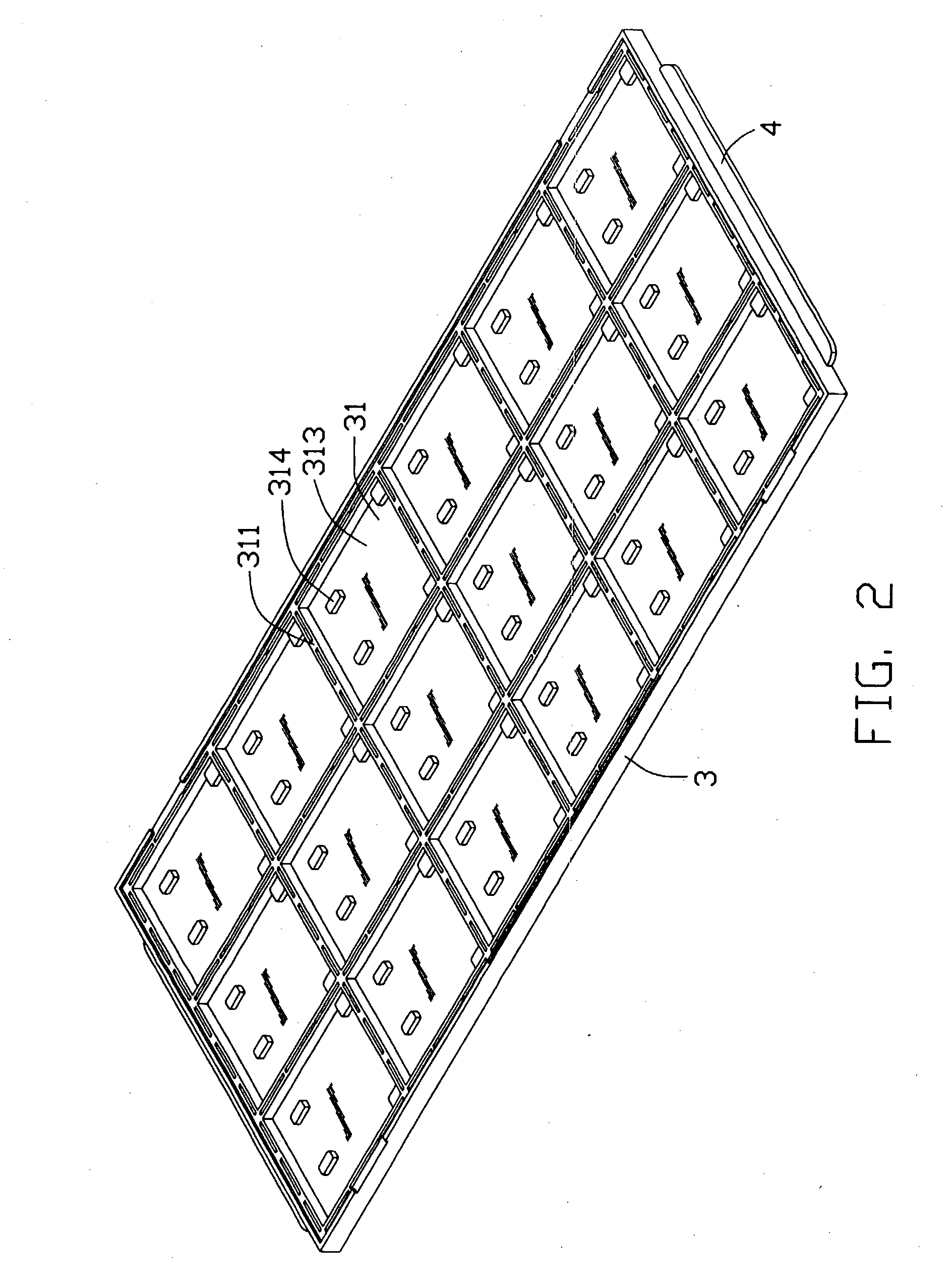
[0017] The packaging tray 2 comprises an elongate base 3, and a pair of ears 4 formed respectively on opposite ends of the base 3. The base 3 comprises a number of supporting portions 31 arranged in a regular rectangular array. Each supporting po...


PUM


Abstract

A packaging tray (2) includes an elongate base (3). The base includes supporting portions (31) for receiving CPU sockets (1) therein. Each supporting portion includes four sidewalls (311), and a bottom wall (313) having an upper surface and a lower surface. Each sidewall forms an inwardly extending rib (312). Four standoffs (314) are formed on the lower surface. When mounting the CPU sockets on the upper surfaces, each CPU socket rests on the corresponding ribs, and solder balls of the CPU socket are supported by the corresponding upper surface. Thus, in handling of the CPU sockets, the solder balls are unlikely to sustain damage. Conversely, the CPU sockets can be reverse mounted on the lower surfaces. The solder balls of each CPU socket are located in a horizontal plane face up, with the standoffs supporting the CPU socket. The solder balls can be accurately inspected by a flatness inspection device.

Description

[0001] 1. Field of the Invention[0002] The present invention relates to a packaging tray, and particularly to a packaging tray used for receiving a plurality of components such as electrical connectors therein, and providing easy and safe transportation and handling of the components.[0003] 2. Description of the Prior Art[0004] Delicate electronic components, such as computer Central Processing Unit (CPU) sockets, are often received in a customized packaging tray. Numerous such trays are stacked into freight containers for transportation and handling of the components. Referring to FIG. 3, CPU sockets 8 (only one shown) are received in a conventional packaging tray 9 such as that disclosed in U.S. application Ser. No. 10 / 266,489. Each CPU socket 8 comprises a multiplicity of solder balls (not shown) on a bottom thereof, and a pick up cap 81 assembled on a top thereof. The pick up cap 81 provides a flat surface for attaching to a vacuum suction device (not shown) on an assembly line....

Claims


Application Information

Patent Timeline
Patent Type & Authority Applications(United States)
IPC IPC(8): H01L21/673H01R13/60
CPCH01R13/60H01L21/67333
Inventor WANG, WEN XIN
Owner HON HAI PRECISION IND CO LTD
Why Eureka
Try Eureka