Centrifugal liquid pump with perimeter magnetic drive

a centrifugal pump and magnetic drive technology, which is applied in the direction of domestic cooling apparatus, lighting and heating apparatus, instruments, etc., can solve the problems of large pump size in the direction parallel to the axis of rotation of the impeller, and the connection of magnets to the impeller sha

Inactive Publication Date: 2004-07-01
INTEL CORP
View PDF5 Cites 54 Cited by
  • Summary
  • Abstract
  • Description
  • Claims
  • Application Information

AI Technical Summary

Problems solved by technology

A significant disadvantage to this type of pump is that the magnets are connected directly to the impeller shaft.
This torque disadvantage require...

Method used


Image

  • Centrifugal liquid pump with perimeter magnetic drive
  • Centrifugal liquid pump with perimeter magnetic drive
  • Centrifugal liquid pump with perimeter magnetic drive

Examples


Embodiment Construction

requires reference to the following drawings, where like numbers indicate like elements throughout.

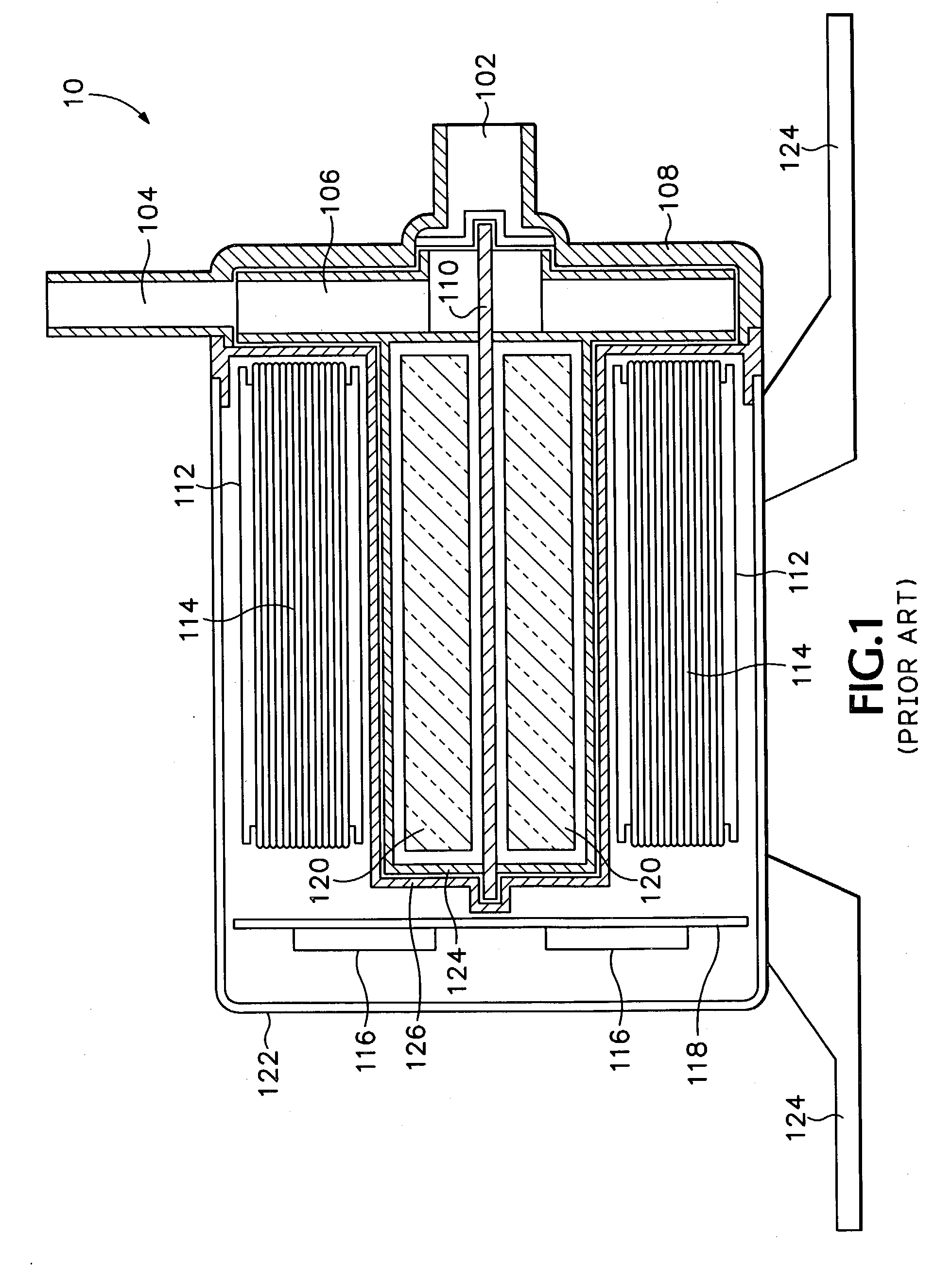
[0012] FIG. 1 is a cross-sectional diagram of a conventional seal-less centrifugal liquid pump with a magnetic drive.

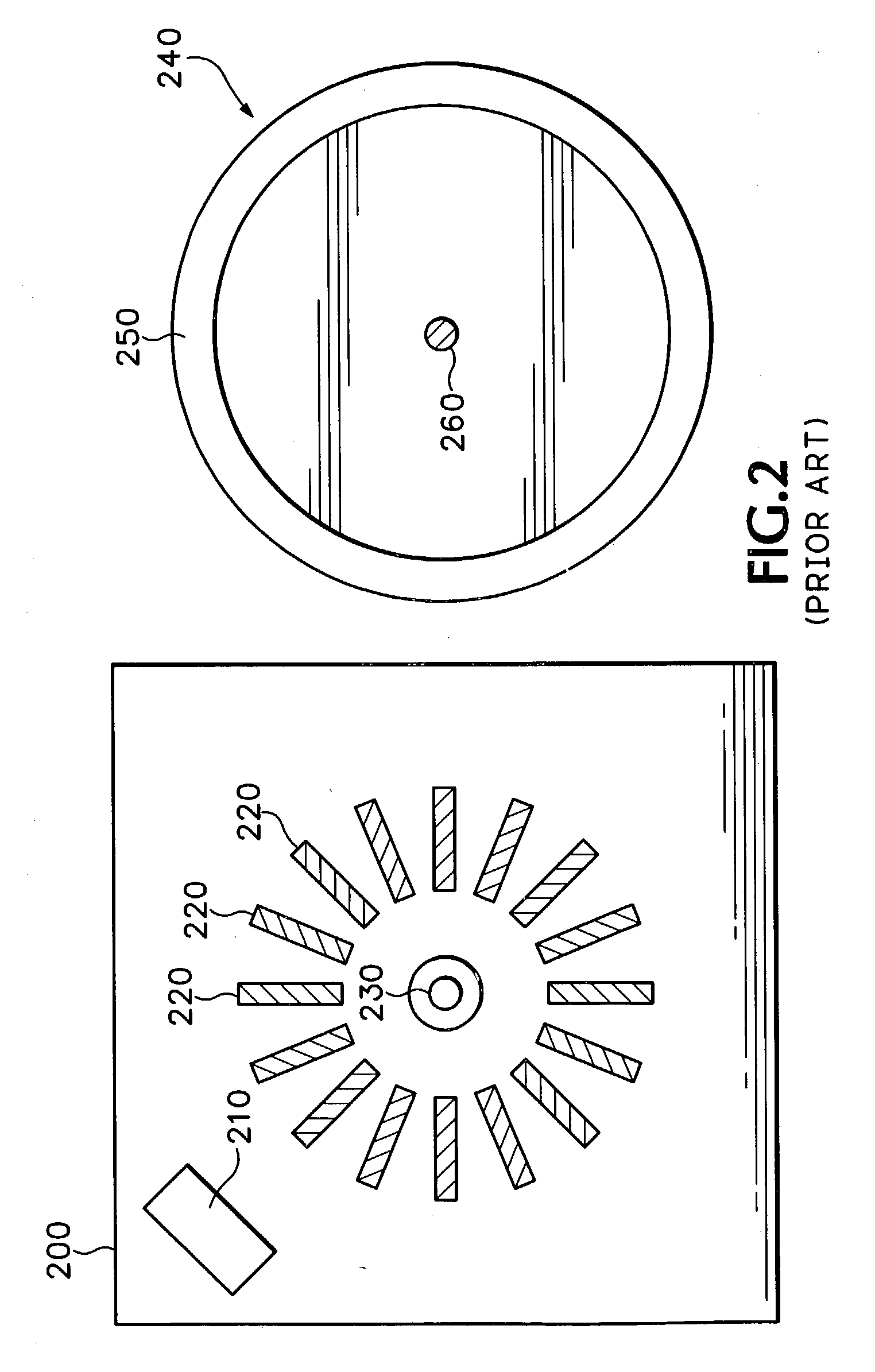
[0013] FIG. 2 is a diagram of some of the main components of a conventional spindle motor of the type used in floppy disk drives.

[0014] FIG. 3 is an isometric view of a centrifugal liquid pump according to an embodiment of the invention.

[0015] FIG. 4 is an isometric view of the bottom of the centrifugal liquid pump shown in FIG. 3.

[0016] FIG. 5 is an isometric view of the top of the impeller assembly of the centrifugal liquid pump shown in FIG. 3.

[0017] FIG. 6 is a cross-sectional diagram of half of the centrifugal liquid pump of FIG. 3.

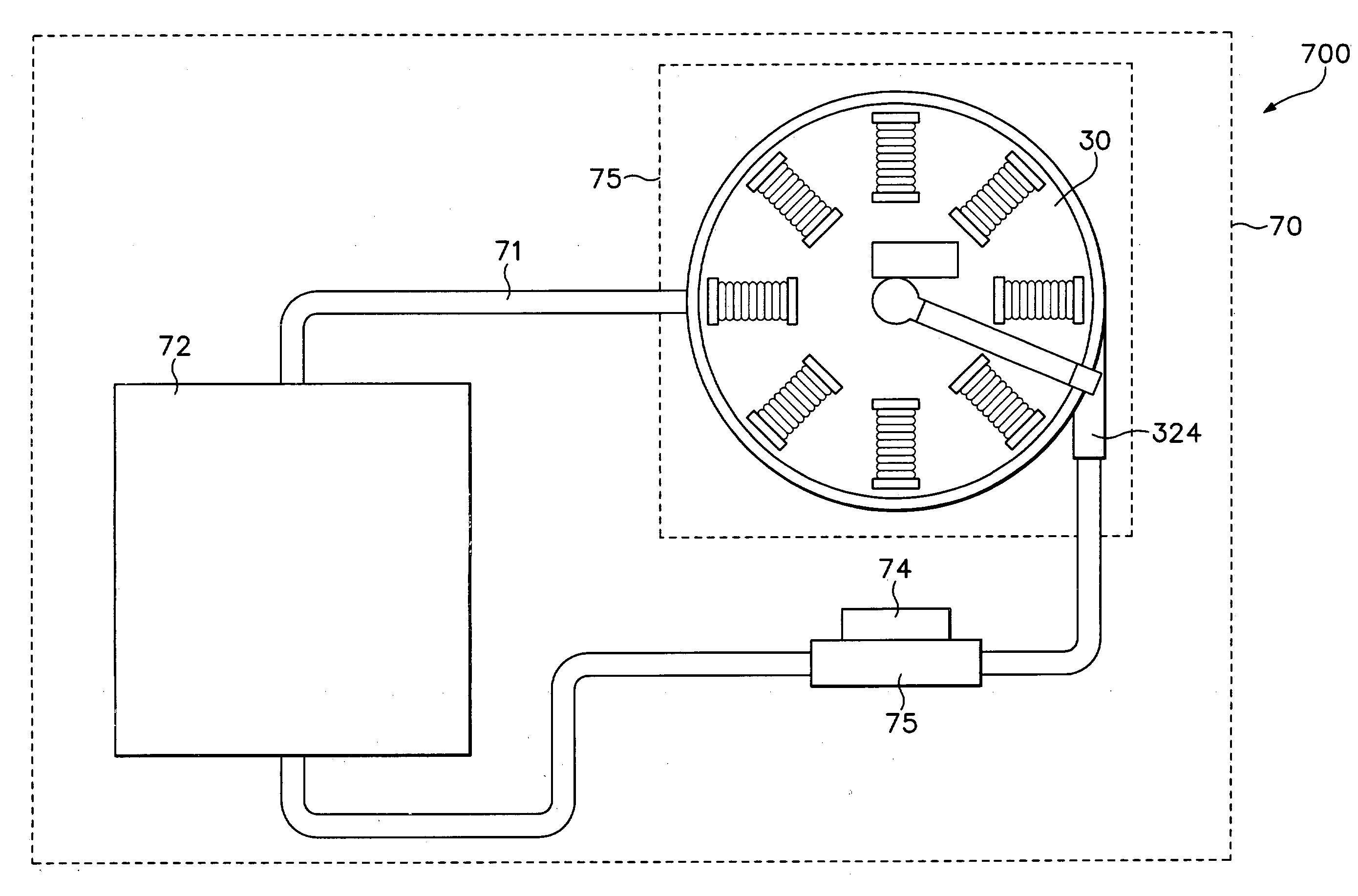
[0018] FIG. 7 is a block diagram illustrating an LC system for a desktop computer.

[0019] Particular embodiments of the invention will now be explained with reference to the drawings. Although the remainder of the discussion will focus on ...


PUM


Abstract

Embodiments of the invention provide a compact, seal-less, centrifugal liquid pump with a perimeter magnetic drive that is substantially smaller than a conventional centrifugal liquid pump having magnets attached directly to the impeller shaft. Because rotational force is applied at the perimeter of the impeller, rather than at the shaft, embodiments of the invention have lower torque requirements and rotational speed, increasing the life of the pump bearings. Additionally, embodiments of the invention may suspend the pump bearings by using a redirected flow of liquid coolant, further increasing the bearing life.

Description

[0001] 1. Technical Field of the Invention[0002] This disclosure relates in general to liquid cooling (LC) systems, and in particular to cooling systems having centrifugal pump devices with magnetic drives.[0003] 2. Description of the Related Art[0004] A cross-sectional diagram of a conventional seal-less centrifugal pump 10 with a magnetic drive is illustrated in FIG. 1. When the pump 10 is operating, liquid is drawn into the pump through an inlet 102 and is expelled from the pump through an outlet 104. An impeller assembly 106 forces the liquid to the outlet 104. The impeller assembly 106 has an impeller shaft 110 connected to impeller magnets 120. The impeller magnets 120 are contained within an impeller magnet housing 124. An inner motor housing 126 separates the impeller magnets 120, impeller shaft 110, and impeller assembly 106 from other motor components within an outer motor housing 122. These components include motor poles 112, motor windings 114, motor electronics 116, and...

Claims


Application Information

Patent Timeline
IPC IPC(8): F04D13/06G06F1/20G11B33/14
CPCG06F1/20G06F2200/201G06F1/26F04D13/0666G05F3/02G11B33/1413
Inventor STEWART, GLENN E.
Owner INTEL CORP
Why Eureka
Try Eureka