
Fast installation/removal structure for circuit board

a technology for installing/removing structures and circuit boards, which is applied in the direction of support structure mounting, electrical apparatus casings/cabinets/drawers, applications, etc., can solve the problems of screw dropping and losing, poor attachment of circuit boards, and time-consuming and cumbersome problems, and achieve the effect of fast installation/removal structur

Inactive Publication Date: 2004-07-01
FIRST INTERNATIONAL COMPUTER
View PDF7 Cites 26 Cited by
  • Summary
  • Abstract
  • Description
  • Claims
  • Application Information

AI Technical Summary

Benefits of technology

"The invention provides a fast installation / removal structure for the circuit board of an electric appliance. The structure allows for easy installation and removal of the circuit board, and is suitable for different types of circuit board designs. The installation is secure and the performance of the components of the electric appliance is improved. The structure includes an upper board, a lower board, and an installation / removal lever. The upper board has hooking grooves and a positioning pin, while the lower board has snap fitting devices that engage with the hooking grooves. The lever is pivotally connected to the lower board and can be manipulated by the user. The invention allows for a fast and convenient assembly of the circuit board, and improves the efficiency of production."

Problems solved by technology

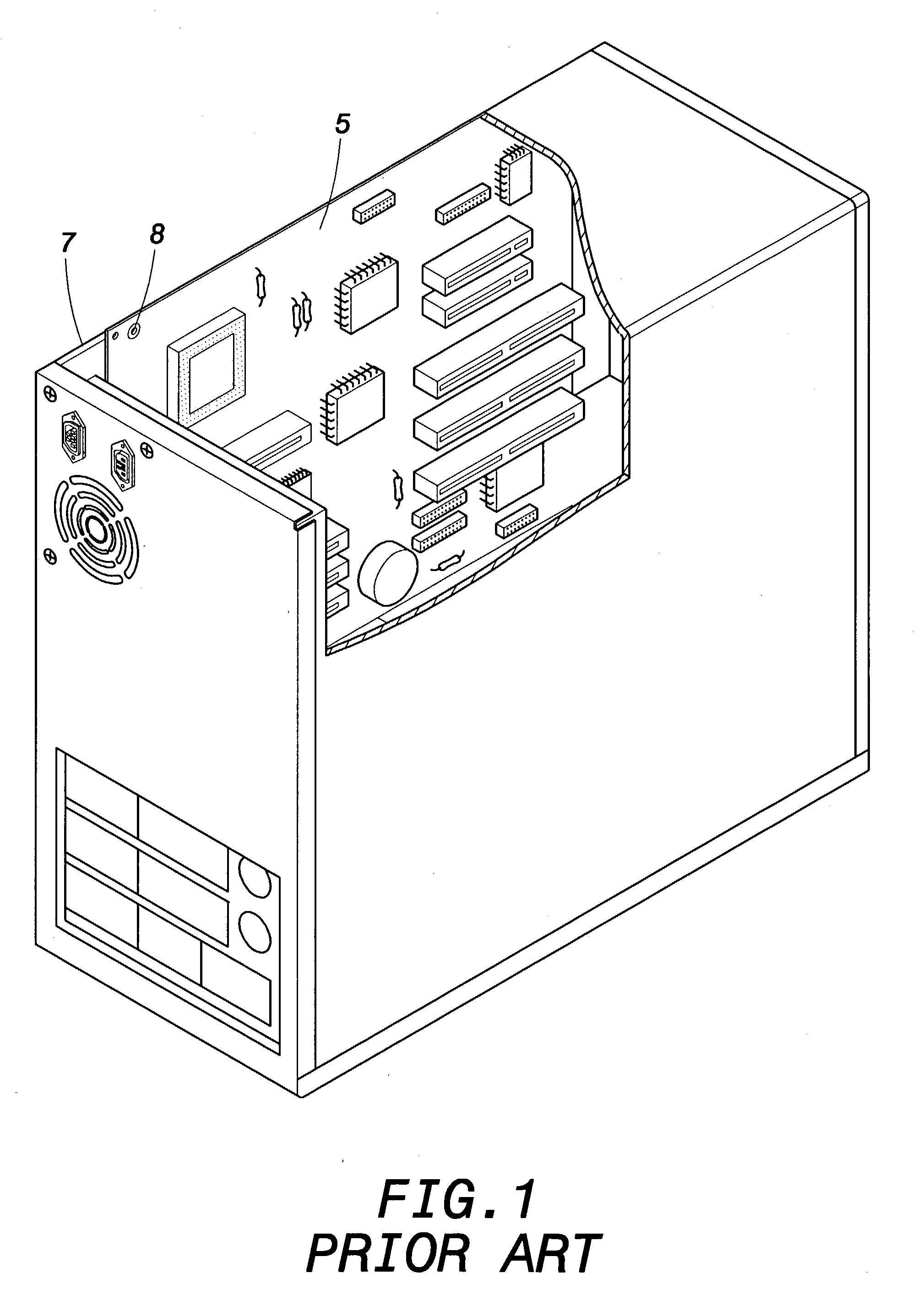
In mass production, a tool is therefore needed to lock multiple screws 8, which is time-consuming and may be cumbersome.
When the circuit board is installed, the manipulation of the screws, usually of small size, may cause the screw to be dropped and lost.
As a result, an insufficient number of mounted fastening screws or, alternatively, the biased engagement of the screws, cause a poor attachment of the circuit board, which may be detrimental to normal operation of the electric appliance.
In the worst situations, the screws may drop into the electric appliance and cause a short-circuit.
Therefore, the conventional installation / removal structure not only is cumbersome, but may also cause a deterioration of the performance of the components of the electric appliance.

Method used


Image

  • Fast installation/removal structure for circuit board
  • Fast installation/removal structure for circuit board
  • Fast installation/removal structure for circuit board

Examples


Embodiment Construction

[0021] Wherever possible in the following description, like reference numerals will refer to like elements and parts unless otherwise illustrated.

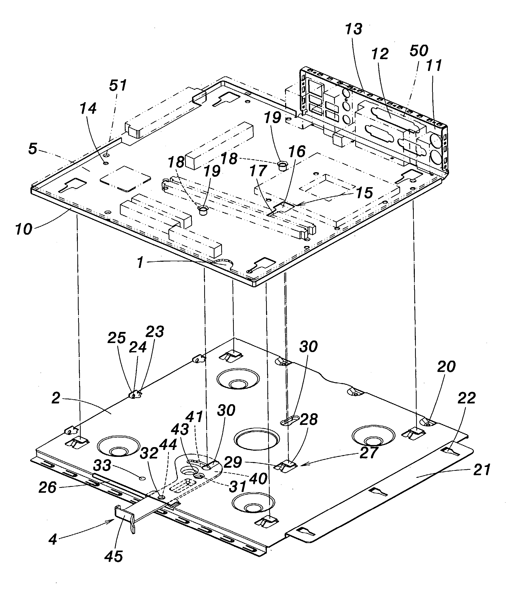
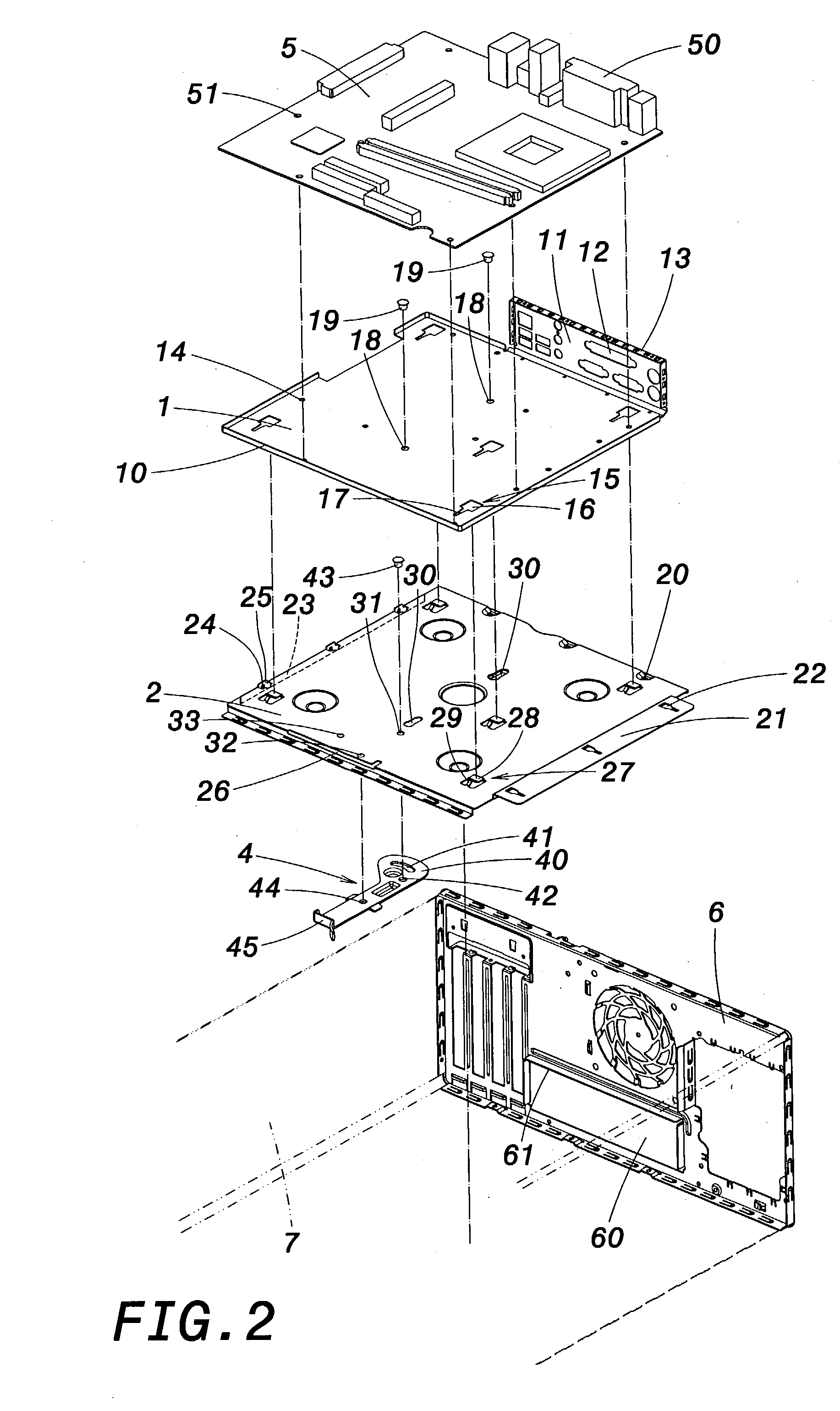
[0022] Referring to FIG. 2, the invention provides a fast installation / removal structure for the circuit board of an electric appliance. In this embodiment, the electric appliance is, for example, a computer and, more particularly, a computer principal unit. However, the skilled artisan will understand that the invention as described hereafter may be also advantageous for various electric appliances. The fast installation / removal structure comprises an upper board 1, a lower board 2, and an installation / removal lever 4.

[0023] The upper board 1 is a thin metallic board formed by, for example, stamping, and is approximately as large as the circuit board 5 of the computer unit. The circuit board 5 includes a connector 50 and threaded holes 51. A peripheral side of the upper board 1 forms a bent edge 10, one portion of which further constitute...


PUM


Abstract

A fast installation / removal structure includes an upper board, a lower board, and an installation / removal lever. The upper board has hooking grooves and at least a positioning pin. The lower board has snap fitting devices and at least a sliding slot through which slidably inserts the positioning pin. A front end of the lever is pivotally connected to the lower board there below, and has a guide groove through which the positioning pin inserts. A rear end of the lever is externally accessible to allow manipulation by the user. With the circuit board securely fastened thereon, the upper board is placed on the lower board. The snap fitting devices respectively engage through the hooking grooves. By turning the lever, the positioning pin slides along the sliding slot to have the snap fitting devices respectively snap fit through the hooking grooves, thereby fastening the upper board to the lower board.

Description

[0001] 1. Field of the Invention[0002] The invention relates to a fast installation / removal structure for a circuit board of an electric appliance. More particularly, the invention provides a fast installation / removal structure that uses a slidable snap fitting to install and remove easily the circuit board so that the maintenance of the electric appliance is convenient.[0003] 2. Description of the Related Art[0004] Among the different components of an electric appliance, such as a computer unit, are usually a circuit board, a power supply, and a casing. The design of the circuit board conventionally determines the principal functions of the electric appliance. The power supply provides the electric power necessary to operate the electric appliance, and the casing externally protects all the components of the electric appliance. The circuit board of the electric appliance is further usually provided with the possibility of multiple extension connections to flexibly accommodate the n...

Claims


Application Information

Patent Timeline
Patent Type & Authority Applications(United States)
IPC IPC(8): H05K7/14
CPCH05K7/142
Inventor CHEN, ARIESCHANG, CHANG LU
Owner FIRST INTERNATIONAL COMPUTER
Learn More