Table frame and table

a table frame and table technology, applied in the field of table frames and tables, can solve the problems of unnecessary time-consuming and costly screw connection, and achieve the effects of reducing stiffness, high safety margin, and high stability

Active Publication Date: 2017-08-10
VEYHL
View PDF0 Cites 24 Cited by
  • Summary
  • Abstract
  • Description
  • Claims
  • Application Information

AI Technical Summary

Benefits of technology

[0005]The table frame according to the invention is suitable for private or commercial use and comprises a first column and a second column for supporting a table top. Each of the columns have a longitudinal axis, an upper end and a lower end. The table frame has a cross member of hollow profile construction by which the first column and the second column are interconnected with each other in the region of their upper ends, the cross member having a longitudinal extension. The cross member allows for a high margin of safety against overturning of the columns and a high grade of stability. The table frame further comprises a first cantilever support mounted on the upper end of the first column and a second cantilever support mounted on the upper end of the second column. Each of the cantilever supports is having two arms extending in an orthogonal direction with respect to the longitudinal extension of the cross member for support of the table top; thereby, table tops of various sizes may be mounted on the columns without the risk of tipping over. Also, thinner table tops with reduced stiffness may be

Problems solved by technology

Thereby, a time-consuming and cost

Method used


Image

  • Table frame and table
  • Table frame and table
  • Table frame and table

Examples


Embodiment Construction

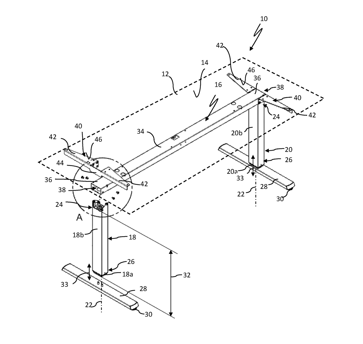
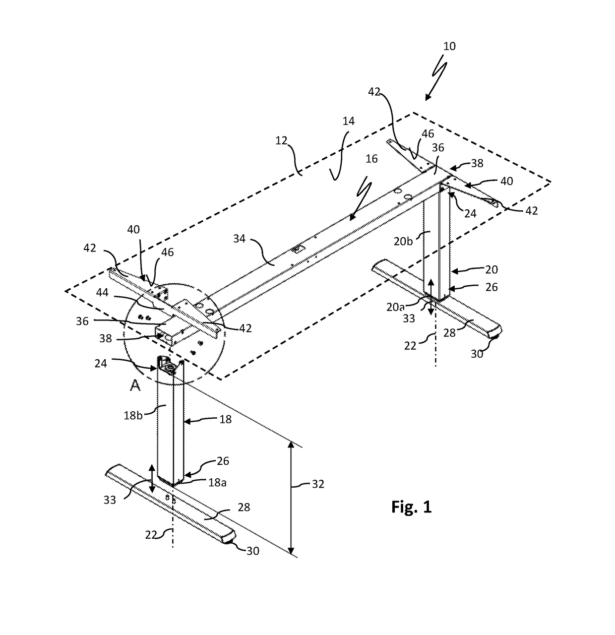
[0024]FIG. 1 shows a perspective view of a partially mounted table 10 which may serve as an office desk, a workbench or the like. The table 10 comprises a table top 12 illustrated in a dashed line and forming a flat working surface 14. The table top 12 is mounted on and supported by a base or table frame 16. The table frame 16 comprises a first column 18 and a second column 20 which both serve as so-called legs of the table 10. A respective longitudinal axis of the columns 18, 20 is designated 22. The columns 18, 20 each have an upper end 24 and a lower end 26. Each column 18, 20 has a stabilizing foot part 28 attached to the lower end 26 thereof in the fully mounted state of table frame 16. The foot part 28 can be positioned on the lower end 26 of the columns 18, 20 such that the table frame 16 has the shape of a so-called T-frame as shown in FIG. 1 or, alternatively, as a so-called C-frame. Guides 30 or casters may be added to the foot part 28 to aid in leveling the table and incr...


PUM


Abstract

A table frame for a table has a first column and a second column for supporting a table top, a cross member of hollow profile construction by which the first column and the second column are interconnected with each other and a first cantilever support mounted on the top end of the first column and a second cantilever support mounted on the top end of the second column. The first and the second column each have two projections at respective top ends thereof. The cross member, at each end section thereof, has a pair of oblong holes disposed on its lower side and through which the two projections of the respective column extend into the cross member. Each cantilever support has a first and a second flange which are arranged spaced-apart from one another, each of the flanges abutting the cross member on a lateral side portion thereof.

Description

BACKGROUND OF THE INVENTION[0001]The present invention relates to table frames and tables for both private and commercial use.[0002]A table is a furniture with a table top forming a flat or essentially flat upper surface used to support objects, for storage, show, and / or manipulation. A common type of table is a desk, which is typically used to hold items that one would need to do work, such as papers, textbooks, or computers. The surface is usually supported from below by several vertical columns or “legs,” which may be adjusted to set the table top of the workstation at a desired height. The legs are usually interconnected at their upper ends by a crossbeam for reason of stability.[0003]The connection between the legs and the crossbeam or cross member is crucial for keeping the table top stable even under load. This is why the connection is usually of a rather complex construction and which may comprise many parts that have to be welded or screwed together. Further, as the tables ...

Claims


Application Information

Patent Timeline
IPC IPC(8): A47B13/02A47B9/04A47B9/20A47B13/00F16B12/10
CPCA47B13/02A47B13/003A47B9/04A47B9/20F16B12/10A47B13/06A47B2200/0013A47B2200/0029A47B2200/0056A47B2200/0061F16B12/52
Inventor BRUDER, WOLFGANGOSWALD, ARTHUR
Owner VEYHL
Why Eureka
Try Eureka