Filament-wound composite coupling

a composite coupling and filament technology, applied in the direction of couplings, gas/liquid distribution and storage, vessel manufacturing, etc., can solve the problems of mechanical failure of metallic couplings, corrosion of traditional metallic pipes, etc., to improve assembly rates and improve axial tensile strength

Active Publication Date: 2006-09-19
NORTH AMERICAN SPECIALTY PROD
View PDF12 Cites 27 Cited by
  • Summary
  • Abstract
  • Description
  • Claims
  • Application Information

AI Technical Summary

Benefits of technology

[0016]The composite coupling includes a cylindrical composite body, with a retainer grooves and ports communicating with the retainer grooves. More specifically, the cylindrical composite body defines an axis and has a first end, a second end, an exterior surface and an interior surface. The first retainer groove is in the interior of the coupling and axially spaced from the first end. The second retainer groove is also in the interior of the coupling and axially spaced from the second end. Ports communicate between the exterior surface and the retainer grooves. The cylindrical composite body is formed of a plurality of concentrically arranged layers of wound filaments in a thermoset plastic matrix, each of the layers characterized by a winding angle opposing the winding angle of the adjoining layers. The coupling preferably also includes means for sealing pipes to be joined to maintain a pressurized flow between the pipes through the restrained joint. Preferably this means for sealing includes O-rings. Preferably, the seal between each pipe and the interior surface of the coupling includes an O-ring. Preferably, the coupling also includes means to index a pipe end so as to position a complementary retainer groove near the pipe end coincident with the first retainer groove. More preferably, the means to index appropriately positions both pipes within the coupling and involves either an integral or unitary radially inwardly directed extension from the interior surface or a snap ring bonded into position. The pipe ends abut such means for indexing to positionally index the complementary retainer grooves coincident to the retainer grooves, by limiting the depth of insertion of the pipe into the end of the composite coupling. The integral pipe stop is preferably symmetric about the axis and is a unitary part of the cylindrical composite body. The snap ring may include a longitudinal cut or gap to allow it to be compressed and then resiliently expand. The ports initiate either a clockwise or counter-clockwise pathway into respective retainer grooves. This feature, in turn, allows the coupling to be reversible while maintaining the pathway orientation for one approaching from an end of the coupling.
[0021]This composite restrained joint pipe coupling overcomes shortcomings of current conventional couplings for larger diameter PVC pipes in pressurized systems. Further, the composite restrained joint pipe coupling allows substantially improved rates of assembly relative to the typical one hour fusion welding processes used to form HDPE joints. Moreover, beside faster assembly than fusion welding processes, the composite restrained joint pipe coupling provides a relatively greater axial tensile strength than a fusion welded HDPE joint. In particular, whereas fusion welded joints of HDPE require on the order of one hour to complete, joints may be assembled between two pipes with the composite coupling of the present invention in less than 15 minutes, preferably less than 10 minutes and most preferably in from about 5 to about 7 minutes. Further, the composite coupling of the present invention, used with appropriate PVC pipes, can be used to assemble joints safely rated for internal pressures of 160 psi in 16 inch pipe systems. Preferably, such PVC pipe and composite coupling joint systems can be used at pressures of 200 psi or more.
[0023]In another embodiment, the present invention is a non-metallic corrosion resistant coupling restrained joint including large diameter PVC pipes and couplings of filament wound fiber reinforced thermoset composites. The restrained joint pipe coupling joints also overcome the problems of conventional coupling joints for larger diameter PVC pipes in pressurized systems and are assembled with improved rates of assembly over fusion welding processes and are joints characterized by improved axial tensile strength.

Problems solved by technology

Traditional metallic pipes are subject to corrosion from some potable waters.
Metallic couplings are also subject to failures, not just from corrosion but also from mechanical failure in response to both radially and axially directed forces.
Such joint disrupting forces originate in frequent and occasionally substantial fluctuations in pressure and / or water flow.
Preparation of each metallically coupled joint along with the often required concrete mass restraining the mechanically coupled joint is particularly problematic.
Joining plastic pipes, however, remains a challenge.
In particular, plastics often have a slick or slippery surface relative to surfaces on metallic materials.
Each of these materials, however, comes with its own challenges in being acceptable as a large diameter pipe material.
As will be explained, these challenges often involve difficulties in joining pipes to form a distribution system.
However, HDPE large diameter pipes are relatively expensive.
Moreover, connecting two HDPE large diameter pipes is both costly and time consuming.
The fusion welding process requires about an hour to complete each joint and further requires the on-site presence of both significant large equipment and skilled labor.
Attempts to substitute unskilled labor can result in defective fusion HDPE joints characterized by unacceptable axial tensile strength.
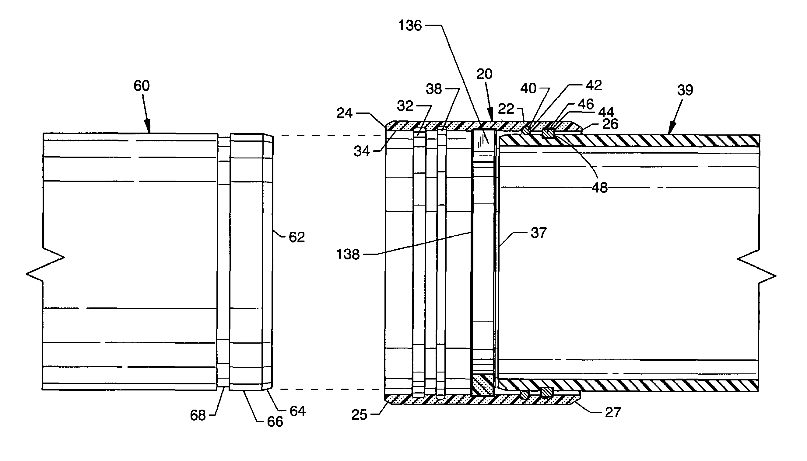
Currently available PVC 16 inch diameter water distribution systems, however, are operated at only 90 psi due to the limited pressure rating of the current PVC pipe couplings used in preparing joints between PVC pipes.
The inventor has investigated extensively and discovered poor pressure performance of the current PVC pipe couplings relates to failure to withstand the hoop stresses associated with higher pressures, such as in the ASTM D2241 qualification test.
Susceptibility to high pressure might be caused by insufficient wall thickness of the couplings about the internal O-ring grooves.
As higher system pressures further expand the PVC coupling adjacent to the O-rings, a leak occurs at one of the two O-rings.
Such an undesired expansion thereby results in a water distribution system failure and, therefore, is the cause of the lower 90 psi pressure limitation.
As noted above, this thickness is insufficient to resist system failure at 200 psi.
Such scorching or burning unacceptably degrades the physical properties of the PVC material.
Moreover, it is thought that excessively thick extrusions fail to achieve a desirable level of “fusion” and thus are plagued by insufficient strength.
It was concluded that an experimental coupling prepared from an approved PVC mixture as a billet with 2 inch thick walls of degraded PVC material would not pass the performance tests indicated in ASTM D2241 and would not yeild a water distribution system having the desired performance reliability.
Prior attempts to constrain the above-mentioned radial expansion in current PVC couplings with supplemental bands or rings of appropriately situated fiberglass reinforcement have failed due to underlying expansion and eventual bursting of the underlying PVC adjacent an O-ring groove when tested at appropriate internal pressure.
However, experimental reinforced HDPE couplings demonstrated unacceptable axial tensile strength, presumably due to the inherent poor compressive strength of HDPE.
The butt welding of the two halves proved to be not feasible as glass fibers migrated to the surface edge during the heating operation.
The presence of the glass made it impossible to form a leak proof bond in the butt welded coupling.
This approach failed because good consolidation was not achieved and water migration through the coupling wall was observed during hydrostatic testing.
This approach failed because of water permeation through the walls of the experimental couplings.
Furthermore, in addition to the unacceptable water permeation characteristic, machining of the spline and O-ring grooves proved a challenge and, when finally machined and tested, the experimental couplings still tended to split circumferentially.
Such joining arrangements require that the pipes themselves are filament wound and do not take advantage of the more economical PVC pipes.
Clearly, an improved coupling for PVC pipe was still needed and a simple solution did not appear available.

Method used


Image

  • Filament-wound composite coupling
  • Filament-wound composite coupling
  • Filament-wound composite coupling

Examples


Embodiment Construction

[0034]By “large diameter pipe” herein is primarily meant pipes of 16 inches OD or greater. Two preferred pipes, useful in practicing several aspects of the present invention, are available from Certainteed Corporation, Valley Forge, Pa. as C905 / RJ™ DR25 (part number 29128) and C905 / RJ™ DR18 (part number 29127) Restrained Joint PVC Pipe, which are both 20 foot polyvinyl chloride pipes of about 17.4 inch outer diameter with a complementary retaining groove located about 3.610 inches from each end of the pipes and thus capable of use with the Certa-Lok™ Restrained Joint system of CertainTeed Corporation. Another preferred pipe is Certa-Lok™ Well Casing pipe which is a 20 foot PVC pipe having an outside diameter of about 16 inches, also available from CertainTeed Corporation. Use of these preferred pipes with fiber-wound composite couplings of the present invention typically and preferably requires a 0.375 by 0.625 rectangular cross-section nylon spline of about 58 inches in length (Cer...


PUM

PropertyMeasurementUnit
winding angleaaaaaaaaaa
outer diameteraaaaaaaaaa

Abstract

A filament-wound composite coupling for use in assembling a restrained joint between large diameter pipes with complementary retaining grooves, such as 16 inch or larger outer diameter polyvinyl chloride pipes. The coupling has first and second ends and ported retaining grooves associated with each end. Preferably, the coupling also includes O-ring seals and a pipe stop to index the pipes to be coupled. The composite coupling has a cylindrical composite body with a plurality of concentrically arranged layers of wound filaments in a thermoset plastic matrix. Each of the layers is characterized by a winding angle opposing the winding angle of the adjoining layers.

Description

BACKGROUND OF INVENTION[0001]The present invention relates to a non-metallic connecting device for pipes conducting pressure medium, the non-metallic connecting device being characterized by the capacity to accept an insertable and separable insert to restrain a pipe end within the connecting device, and in particular, the present invention relates to a filament-wound composite connecting device for preparing a restrained joint between large diameter pipes conducting pressure medium.[0002]Potable water is distributed at the lowest cost per mass of any commodity. Traditional water distribution systems employed large diameter metallic pipes interconnected by joints featuring complex metallic couplings. Traditional metallic pipes are subject to corrosion from some potable waters. Metallic couplings are also subject to failures, not just from corrosion but also from mechanical failure in response to both radially and axially directed forces. Such joint disrupting forces originate in fre...

Claims


Application Information

Patent Timeline
Patent Type & Authority Patents(United States)
IPC IPC(8): F16L37/00
CPCF16L37/148F17C2209/2154
Inventor ZARYNOW, JOHN
Owner NORTH AMERICAN SPECIALTY PROD
Why Eureka
Try Eureka