Floor panel and method of laying a floor panel

a technology of floor panels and axis angles, applied in the direction of load-supporting elements, structural elements, building components, etc., can solve the problems of easy pivoting about an axis parallel to the first side edge, panel core swelling, etc., and achieve the effect of durable latching and quick and straightforward laying

Active Publication Date: 2004-07-08
VÄLINGE INNOVATION AB
View PDF99 Cites 296 Cited by
  • Summary
  • Abstract
  • Description
  • Claims
  • Application Information

AI Technical Summary

Benefits of technology

0008] This object is achieved according to the invention by a floor panel having the features of claim 1. The methods

Problems solved by technology

The disadvantage with such a profile is the fact that, in order to ensure a minimal joint on the surface of the panel, the connecting means on the longitudinal side have to be designed such that there is prestressing in the connection since, otherwise, there is too great a gap between two laid panels, and dirt and moisture can penetrate therein, which results in the panel core swelling up.
Furthermore, prestres

Method used


Image

  • Floor panel and method of laying a floor panel
  • Floor panel and method of laying a floor panel
  • Floor panel and method of laying a floor panel

Examples


Embodiment Construction

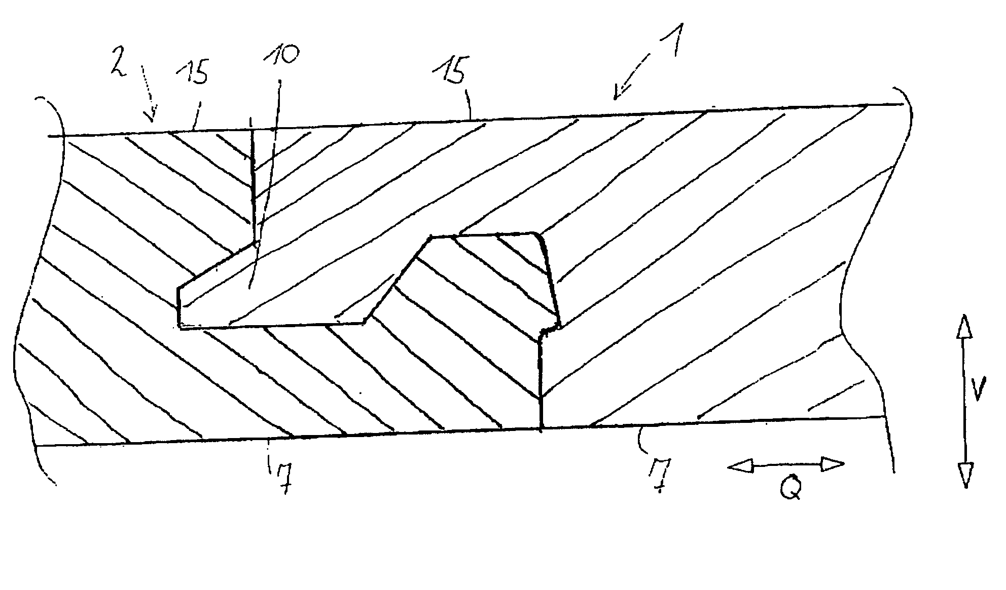
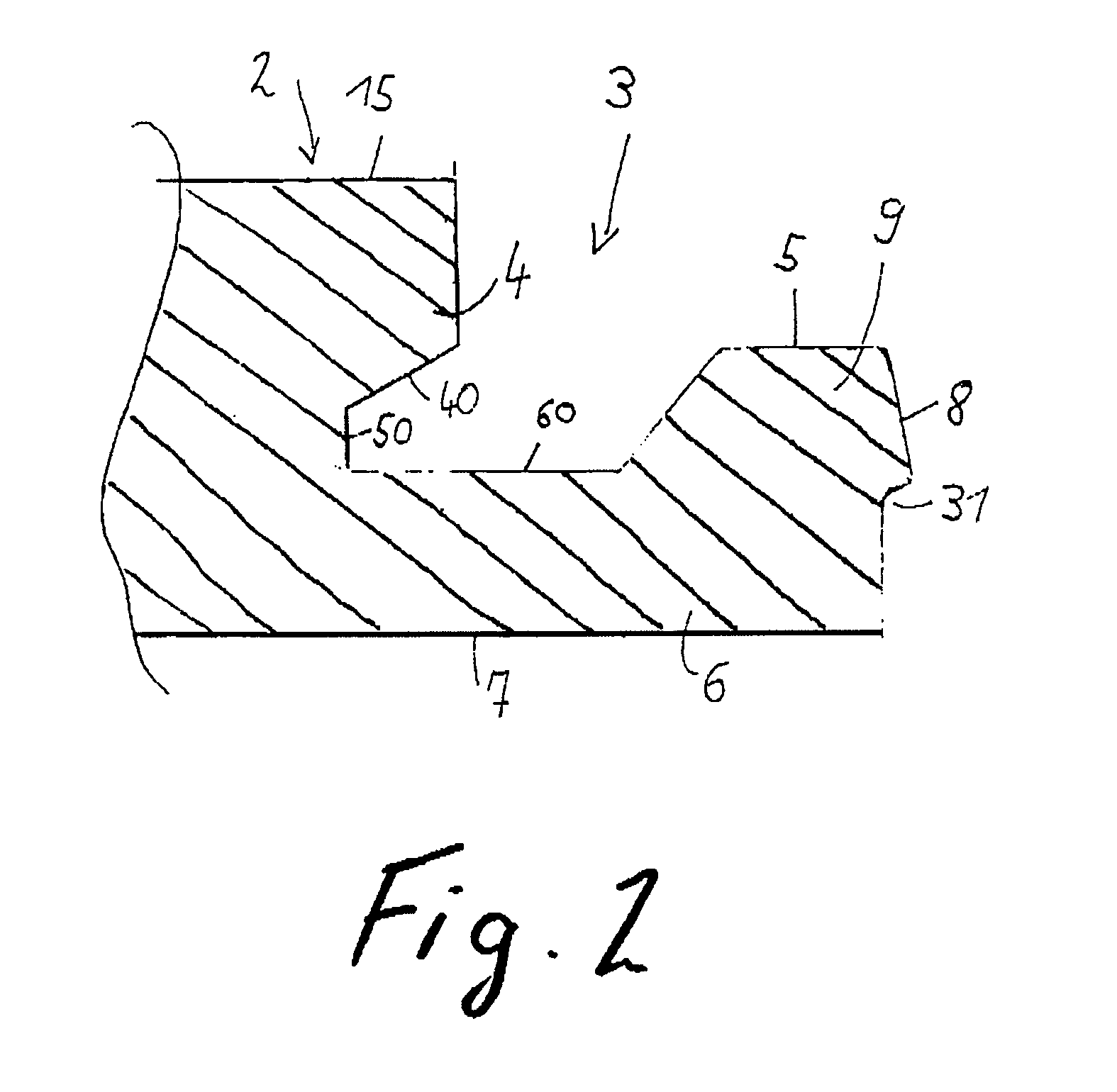
[0052] FIGS. 1 and 2 show a floor panel 1 which comprises a medium-density or high-density fiberboard (MDF or HDF). On its top side 15, the floor panel 1 may be provided with a decorative layer 16 which may be formed, for example, by a paper layer which exhibits a woodgrain and is coated with a synthetic-resin layer serving to protect against wear. A sound-insulation layer may be adhesively bonded to the underside 7 in order to improve the footfall-sound properties of the laid floor panels. As an alternative to using an HDF or MDF board, the panel 1 may be produced from an OSB material (orientated strands board), it being possible in this case to dispense with a decorative layer 16. The panel 1 is provided with a tongue 10 on a first side edge, preferably on the longitudinal side of the panel 1, and with a recess 3 on the opposite, second side edge.

[0053] The recess 3 and the tongue 10 run over the entire length of the side edges. An outwardly projecting tip 101 with a vertical fron...


PUM


Abstract

Floor panel which is provided with means for releasably connecting at least two panels, it being the case that a tongue is formed to extend in the longitudinal direction of the side edge and corresponding recess is formed opposite it, that the recess comprises a top lip and a bottom lip, and the bottom lip forms a shoulder with a front shoulder side, said shoulder blocking the panels in the transverse direction (Q), that an undercut is adjoined by a recess, with a bearing region which corresponds to the shoulder, and a wall, which, with the front shoulder side in the installed state, is located opposite the latter, and that corresponding form-fitting elements are formed on the wall and the front shoulder side, said form-fitting elements, in the installed state, engaging one inside the other and bringing about locking in the vertical direction (V), and an underside of the tongue and a top side of the bottom lip runs parallel to the top side.

Description

[0001] 1. Field of the Invention[0002] The invention relates to a floor panel and to a method of laying a floor panel.[0003] 2. Background Description[0004] WO 01 / 75247 A1 discloses a floor panel which, on a first side edge, has connecting means for locking in the transverse and vertical directions. These locking means are arranged on the longitudinal side of the panel and bring about locking by the connecting means being introduced and pivoted into a corresponding recess of a second panel. The transverse side of the panel has two snap-in hooks which, when the panels are laid, are intended to engage in corresponding undercuts of an adjacent panel and to hinder the vertical movement between the laid panels. The two snap-in hooks are located vertically one above the other.[0005] The disadvantage with such a profile is the fact that, in order to ensure a minimal joint on the surface of the panel, the connecting means on the longitudinal side have to be designed such that there is prest...

Claims


Application Information

Patent Timeline
IPC IPC(8): E04F15/02
CPCE04F15/02E04F15/181E04F2201/0115E04F2201/0138E04F2290/043E04F2201/026E04F2201/0523E04F2201/0529E04F2201/023
Inventor HECHT, HENDRIK
Owner VÄLINGE INNOVATION AB
Why Eureka
Try Eureka