Lens barrel, image obtaining unit, and method for assembling same

a technology of image obtaining unit and lens barrel, which is applied in the field of lens barrel, image obtaining unit, and assembling method, can solve the problems of difficult to accurately insert the lens into the lens frame by free fall, difficult to use tweezers to hold such a small lens, and difficult to accurately insert the lens into the lens frame. , to achieve the effect of easy assembly, accurate positioning and accurate positioning of the lens in the lens base componen

Active Publication Date: 2018-04-10
KONICA MINOLTA INC
View PDF13 Cites 0 Cited by
  • Summary
  • Abstract
  • Description
  • Claims
  • Application Information

AI Technical Summary

Benefits of technology

[0065]According to the present invention, the lens frame which holds the lens inside is divided between a cylinder body component and a lens base component. Therefore, there is no need to drop the lens in the lens frame. First, the lens is adhered and fixed to the lens base component and then the lens base component is adhered and fixed to the cylinder body component. With this, the components can be easily assembled.
[0066]A tip surface of the lens is comfortably supported by the inner side surface of the tip base portion, and the outer circumferential surface is matched with the inner side surface of a side wall portion to be accurately positioned.
[0067]Since the lens base component is divided from the cylinder body component, the lens base component is not so long. When the side wall portion is in a full circle shape, the hole is not too deep, and when the side wall portion is formed in an arc shape, the structure is not a hole surrounding the lens. Therefore, it is easy to accurately position the lens in the lens base component. Moreover, the following process becomes easy to perform, to confirm whether the adhesive is suitably spread in a suitable amount, to accurately temporarily fix the lens with the lens base component in the hardening process of the adhesive, and to test the accuracy of the fixed position and the sealing performance after the adhesive hardens.
[0068]At least a portion of the upper surface of the side wall portion composes a positioning surface and positions the axis direction position of the imaging unit or the imaging fiber inserted from the end opening of the cylinder body component.
[0069]The lens is provided in a position shifted from the central axis of the inserting portion where the member of the cylinder body component is inserted, and the positioning surface of the upper surface of the side wall portion is shifted to the opposite side that the lens is shifted. Therefore, the thickness of the side wall portion to the shifted side, that is, the hardness of the side wall portion and the necessary width of the positioning surface can be secured while suppressing the occupying rate of the side wall portion in the radial direction to a low value. Since the necessary width of the positioning surface is secured, the imaging unit or the imaging fiber can be reliably latched. Since the hardness of the side wall portion is secured, the accuracy of positioning the lens and the imaging unit or the imaging fiber is highly secured. Since the occupying rate of the side wall portion in the radial direction is low, the small diameter of the lens barrel can be easily maintained and enhanced.
[0070]Therefore, according to the present invention, even if the lens barrel is long and has a small diameter, the adhesive can be filled in the suitable position, the airtightness and the watertightness can be secured, and the configuration can be easily assembled.

Problems solved by technology

In a lens barrel composing a tip portion of an endoscope with a small diameter of about 1 mm, when the lens frame is a small diameter or the lens frame is long in an optical axis direction (therefore, the lens inserting hole is deep), it is difficult to insert the lens.
Undoubtedly, using tweezers to hold such a very small lens is very difficult, and accurately inserting the lens into the lens frame by free fall is also very difficult.
The hardening shrinkage of the adhesive causes pulling force in the thrust direction.

Method used


Image

  • Lens barrel, image obtaining unit, and method for assembling same
  • Lens barrel, image obtaining unit, and method for assembling same
  • Lens barrel, image obtaining unit, and method for assembling same

Examples


first embodiment

[0089]First, the first embodiment of the present invention is described.

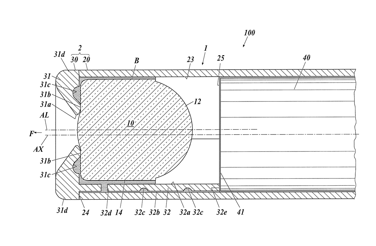
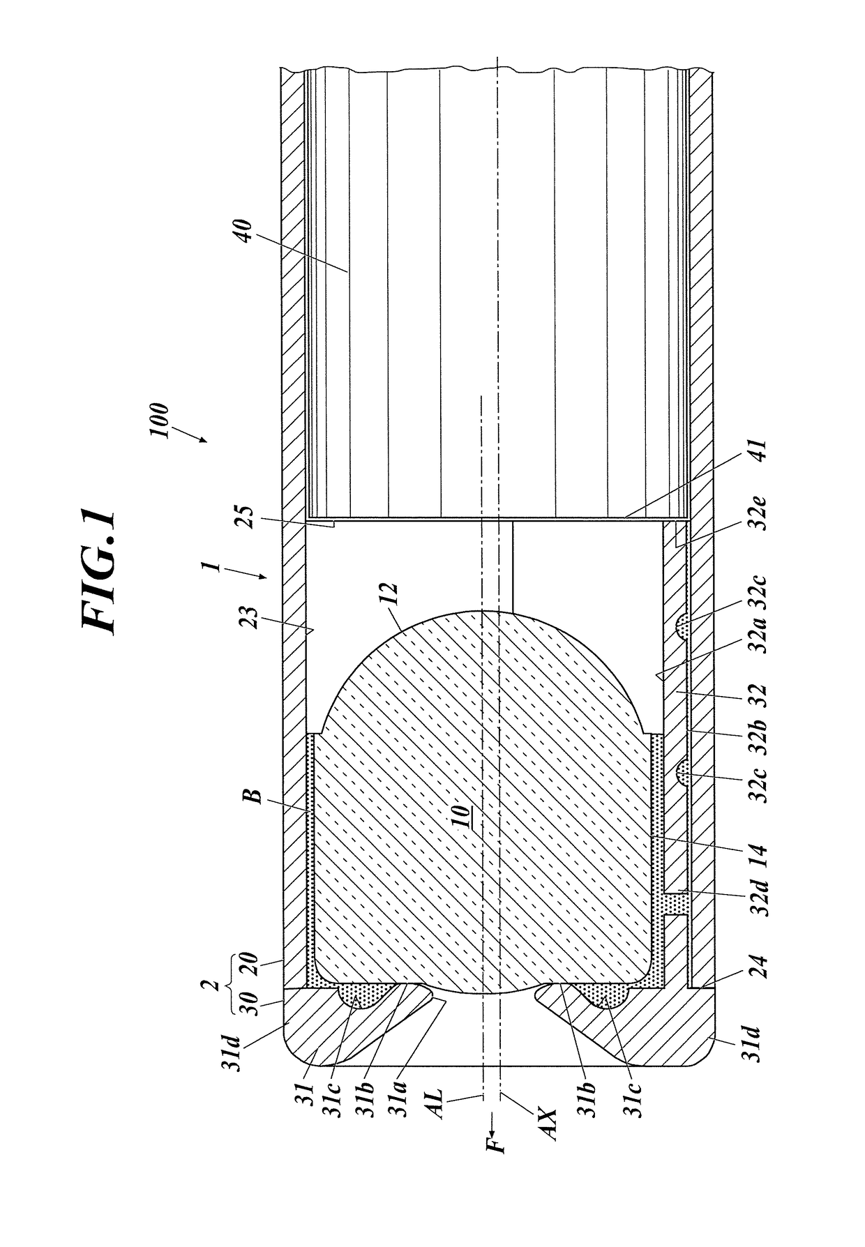
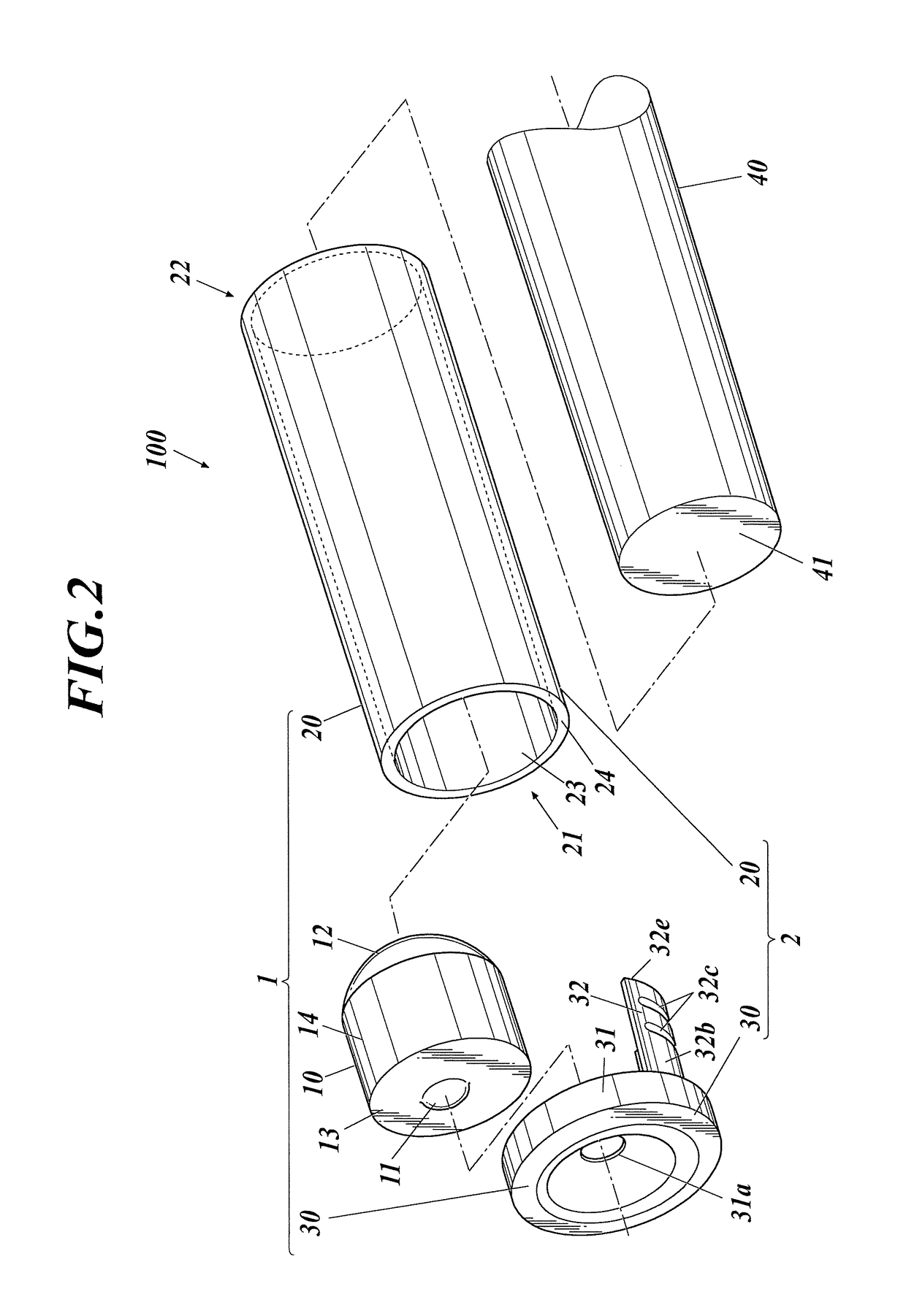
[0090]As shown in FIG. 1 and FIG. 2, an image obtaining unit 100 is composed by attaching a lens barrel 1 to a tip portion of an imaging unit or imaging fiber 40. The lens barrel 1 includes a lens 10 which images an image of a subject, and a lens frame 2 which holds the lens 10 inside. The lens frame 2 includes a cylinder body component 20 and a lens base component 30 assembled together. In the lens barrel 1 and the image obtaining unit 100, the side where the lens 10 is provided is to be a tip and the opposite side is to be an end. B in the figure shows adhesive and arrow F shows a tip direction.

[0091]The lens 10 includes a tip side optical surface 11 and an end side optical surface 12. The lens 10 is a resin lens formed by injection molding with the end side optical surface 12 being the concave lens surface. Any lens surface with a convex shape, a concave shape or a planar shape can be applied for the tip side...

second embodiment

[0117]Next, the second embodiment of the present invention is described.

[0118]According to the first embodiment, the arc shaped side wall portion 32 is employed as the lens base component 30.

[0119]According to the present embodiment, as shown in FIG. 7, a full circle side wall portion 33 is employed as the lens base component.

[0120]The lens 10 is shifted from the central axis AX and the upper surface 33e which is the positioning surface is shifted to the opposite side that the lens 10 is shifted. Therefore, there is a thinnest portion 33f to the side where the lens 10 is shifted. The lens barrel tends to become larger because it is difficult to form the thinnest portion 33f thinner and more accurately, and the full circle side wall portion 33 is provided in a full circle of the outer circle of the lens 10 inside the cylinder body component 20. Moreover, it is advantageous from the point of assembly, filling adhesive and testing to open around the lens 10 180 degrees or more as in th...

third embodiment

[0122]Next, the third embodiment of the present invention is described.

[0123]The present embodiment is an embodiment which employs the lens 10A with a gate edge 15, formed when the lens is formed by injection molding, left projecting from the outer circumferential surface 14 as shown in FIG. 8.

[0124]The lens base component employed in the present embodiment is shown in FIG. 9A and FIG. 9B.

[0125]A vertical groove 32g to store the gate edge 15 is formed in the arc shaped side wall portion 32A as shown in FIG. 9A, and a vertical groove 32h to store the gate edge 15 is formed in the arc shaped side wall portion 32B as shown in FIG. 9B.

[0126]With this, the lens can be embedded even if the gate edge 15 is left, the process to remove the gate edge 15 is not necessary, and the productivity is enhanced.

[0127]The vertical groove 32b is formed with the bottom of the groove remaining, and the vertical groove 32h is formed so as to divide the arc shaped side wall portion 32B into two.

[0128]Moreo...


PUM

PropertyMeasurementUnit
diameteraaaaaaaaaa
diameteraaaaaaaaaa
outer diameteraaaaaaaaaa

Abstract

A lens barrel for imaging a subject; and a lens frame which holds the lens. The lens frame includes a body structure opened at a tip and an end; and a lens base which fixes the lens and is adhered to a tip opening of the body; the lens base includes: a tip base including an opening which exposes a tip side lens optical surface and an inner side which supports the lens; and a circle or arc sidewall extending axially from the tip base; the inner surface of the sidewall is formed along an outer circumference surface of the lens; the inner side surface and the outer circumference are adhered to each other; and a portion of the upper surface of the sidewall is provided toward an end side separated from the far end of the lens to be exposed inside the body.

Description

RELATED APPLICATIONS[0001]This is a U.S. National Phase Application under 35 USC 371 of International Application PCT / JP2013 / 082562 filed on Dec. 4, 2013.[0002]This application claims the priority of Japanese application no. 2012-265870 filed Dec. 5, 2012, the entire content of which is hereby incorporated by reference.TECHNICAL FIELD[0003]The present invention relates to a lens barrel, an image obtaining unit, and an assembling method of the above. Specifically, the present invention relates to a lens barrel and an image obtaining unit composing a small diameter endoscope and an assembling method of the above.BACKGROUND ART[0004]In a typical camera lens barrel, an outer diameter of the lens is relatively large. Therefore, the flange portion of the lens is held with tweezers and the lens is dropped into the lens frame to manufacture the lens barrel. Instead of using tweezers, air is sucked to adsorb the lens with an adsorption pad to hold the lens.[0005]In a lens barrel composing a ...

Claims


Application Information

Patent Timeline
Patent Type & Authority Patents(United States)
IPC IPC(8): H04N5/225B32B37/12A61B1/00A61B1/05A61B1/055G02B23/24B32B37/18G02B7/02B32B37/14
CPCG02B7/025A61B1/00096A61B1/05A61B1/055B32B37/12B32B37/142G02B23/2476H04N5/2253H04N5/2254B32B37/18H04N2005/2255B32B2307/412B32B2551/00H04N5/2257H04N23/555H04N23/57H04N23/55H04N23/54
Inventor JONO, JUNICHINATSUNO, YASUYUKIATARASHI, YUICHI
Owner KONICA MINOLTA INC
Why Eureka
Try Eureka