Modular interface and coupling system and method

a technology of fluid distribution components and modular interfaces, applied in liquid/fluent solid measurement, instruments, electrochemical variables of materials, etc., can solve the problems of little interchangeability of fluid distribution components, lack of modular interfaces or suggested methods, and inability to provide or suggest methods for mounting components to modular interfaces. , to achieve the effect of reducing the cost of doing so

Inactive Publication Date: 2004-07-22
TELEDYNE
View PDF20 Cites 50 Cited by
  • Summary
  • Abstract
  • Description
  • Claims
  • Application Information

AI Technical Summary

Benefits of technology

0013] The present invention is also directed to a method of coupling a fluid distribution component to an interface. The method comprises positioning the fluid distribution component over an opening in the interface. The opening is positioned to receive at least a portion of the fluid distribution component, and the interface includes at least one entering pathway and at least one exiting pathway for a gas or other fluid extending into the opening to provide fluid communication with the fluid distribution component. At least a portion of the fluid distribution component is secured within the opening and allows fluid communication between the fluid distribution component and the interface.

Problems solved by technology

The SP76 Guidelines, however, do not provide or suggest methods of mounting components to the modular interface.
Currently, there is little interchangeability of fluid distribution components, such as gas sensors, in fluid distribution and fluid measuring systems.
Though largely impracticable, if it is possible to interchange one gas sensor with another, doing so is typically time-consuming, costly, and inefficient.
In addition, the multiple variations of tubing and adaptors that may be needed for component interchangeability may reduce the effectiveness of a component to monitor, measure, or sense an incoming stream.
Such reduced effectiveness may occur as a result of, for example, leakage through the seals associated with the adaptors employed.

Method used


Image

  • Modular interface and coupling system and method
  • Modular interface and coupling system and method
  • Modular interface and coupling system and method

Examples


Embodiment Construction

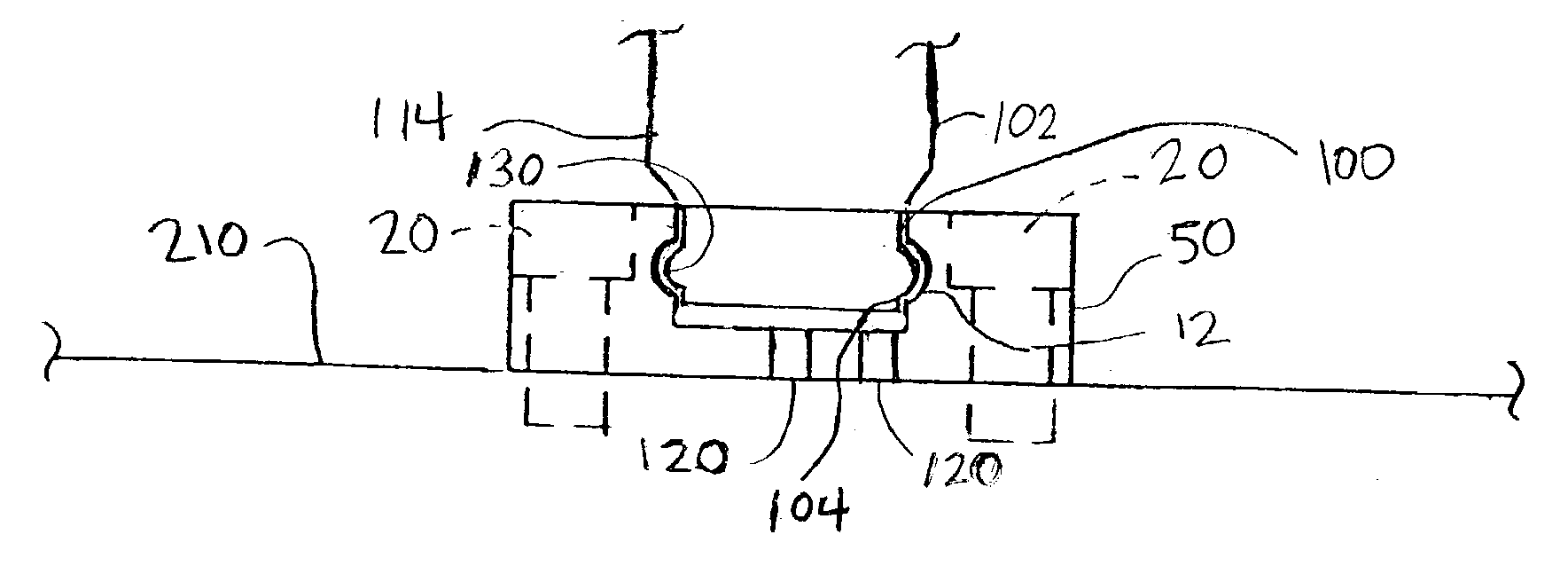
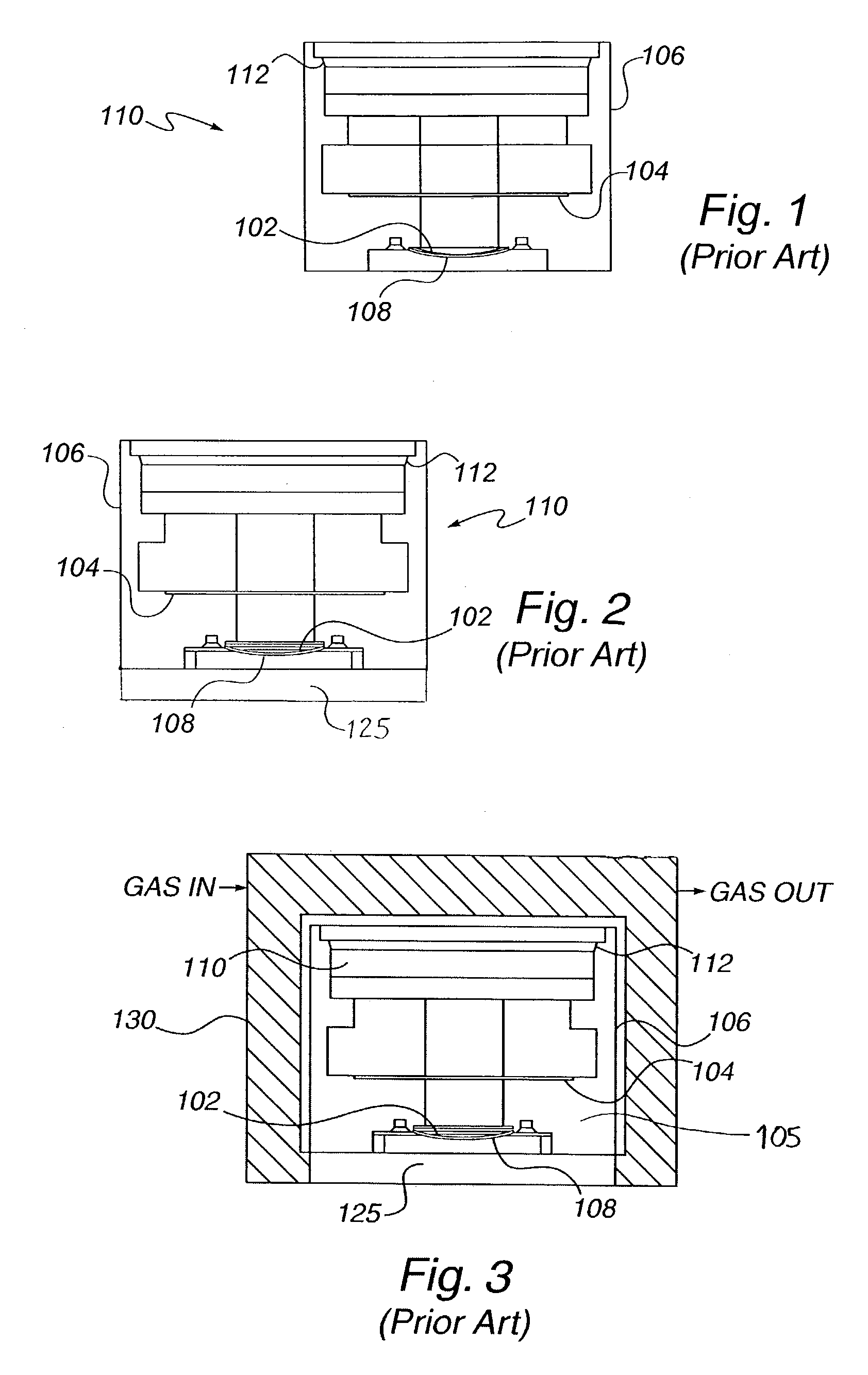
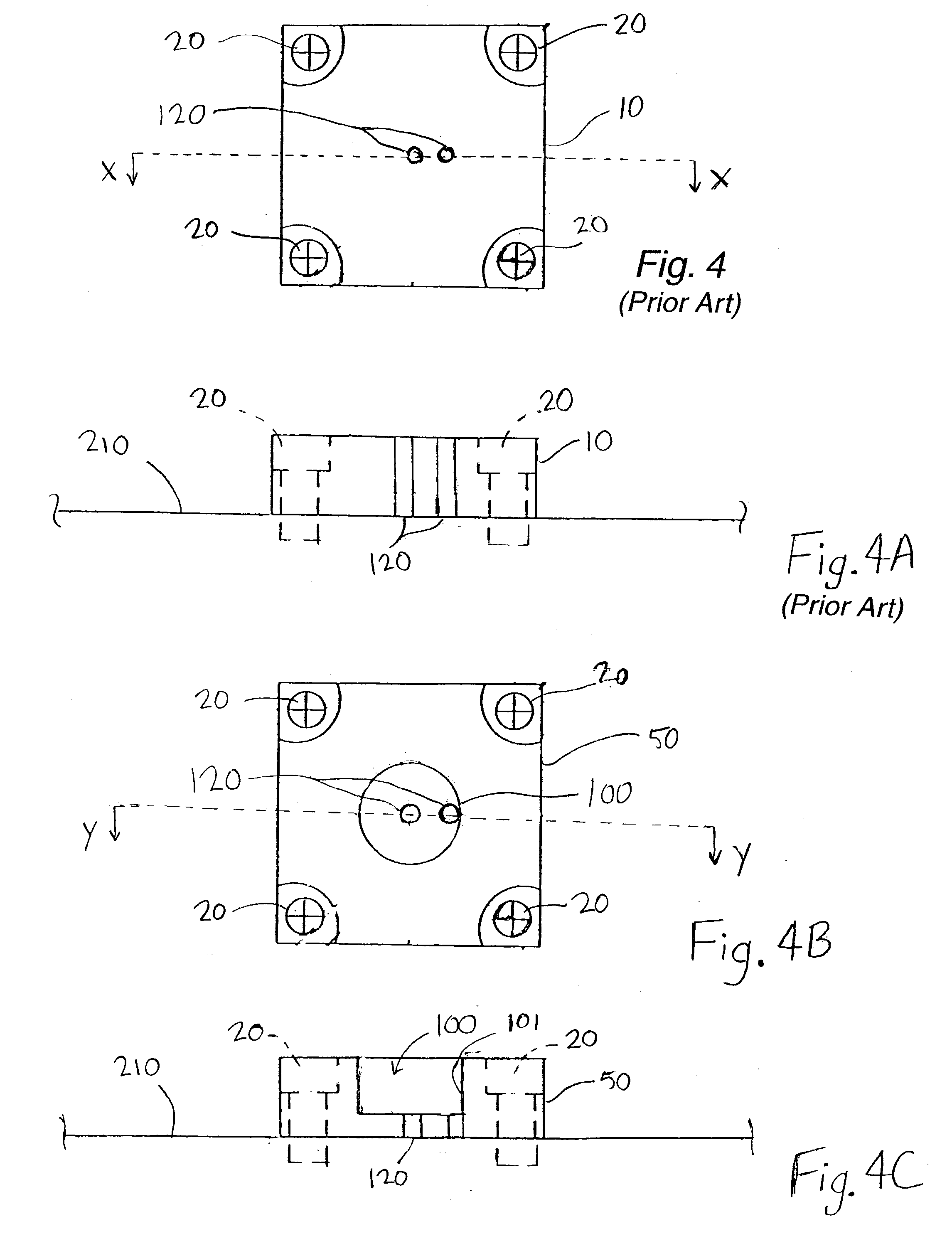
[0025] In the present detailed description of the invention, the invention will be illustrated in the form of a gas sensor adapted for use as a sealed galvanic oxygen sensor. It will be understood, however, that the invention is not limited to embodiment in such form and may have application in any fluid distribution component. Thus, while the present invention is capable of embodiment in many different forms, for ease of description this detailed description and the accompanying drawings disclose only specific forms as examples of the invention. Those having ordinary skill in the relevant art will be able to adapt the invention to application in other forms not specifically presented herein based upon the present description.

[0026] Also, for ease of description, the invention and devices to which it may be attached may be described herein in a normal operating position, and terms such as upper, lower, front, back, horizontal, proximal, distal, etc., may be used with reference to th...


PUM

PropertyMeasurementUnit
heightaaaaaaaaaa
heightaaaaaaaaaa
diameteraaaaaaaaaa

Abstract

An interface for coupling a fluid distribution component to a substrate, the interface including an opening therein for receiving at least a portion of the distribution component, the interface including at least one entering pathway and at least one exiting pathway engaging the opening and providing fluid communication between the fluid distribution component and the substrate. The coupling arrangements of the present invention provide a means by which distribution components, such as gas sensors, of various manufacturer designs may be interchangeable.

Description

[0001] 1. Field of the Invention[0002] This invention relates to a modular interface and a system and method of coupling fluid distribution components, such as gas sensors to substrates.[0003] 2. Brief Description of the Invention Background[0004] FIG. 1 illustrates a typical oxygen sensor 110 such as, for example, a Teledyne Analytical Instruments B2 oxygen sensor available from Teledyne Electronic Technologies, City of Industry, California. The oxygen sensor 110 consists of a cathode 102 and an anode 104 sealed in a housing 106 filled with a suitable electrolyte solution. Oxygen diffuses into the interior of the sensor housing 106 through an oxygen permeable sensing membrane 108. A flexible expansion membrane 112 at an opposite end of the sensor 110 permits expansion or contraction of the electrolyte volume. The sensing membrane 108 is sealed in place by means of press fit, and the expansion membrane 112 is sealed in place by means of heat seal. Oxygen is reduced at the cathode 10...

Claims


Application Information

Patent Timeline
Patent Type & Authority Applications(United States)
IPC IPC(8): G01N27/49G01N33/00
CPCG01N33/0009
Inventor BROY, STEPHEN H.PENSON, KARL F.
Owner TELEDYNE
Why Eureka
Try Eureka