Blade holder

Inactive Publication Date: 2004-07-29
VERMOP SALMON
View PDF34 Cites 14 Cited by
  • Summary
  • Abstract
  • Description
  • Claims
  • Application Information

AI Technical Summary

Problems solved by technology

However, in practical use of this frequently used blade holder, it has turned out that changing the blade clamped into the blade holder is not only complicated and difficult but even dangerous as well.
Due to this, changing a blade becomes on the one hand uncomfortable while on the other hand, even with the slightest lack of care there is a danger of significant injuries from cutting.
The we

Method used


Image

  • Blade holder
  • Blade holder
  • Blade holder

Examples


Embodiment Construction

[0028] A preferred embodiment of the present invention is described here below with reference made to the accompanying drawings.

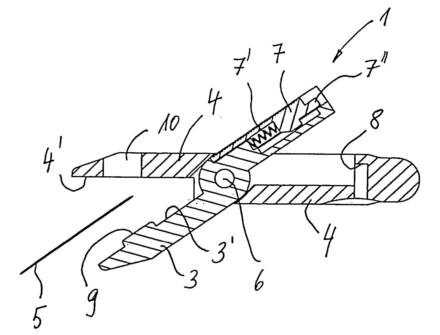
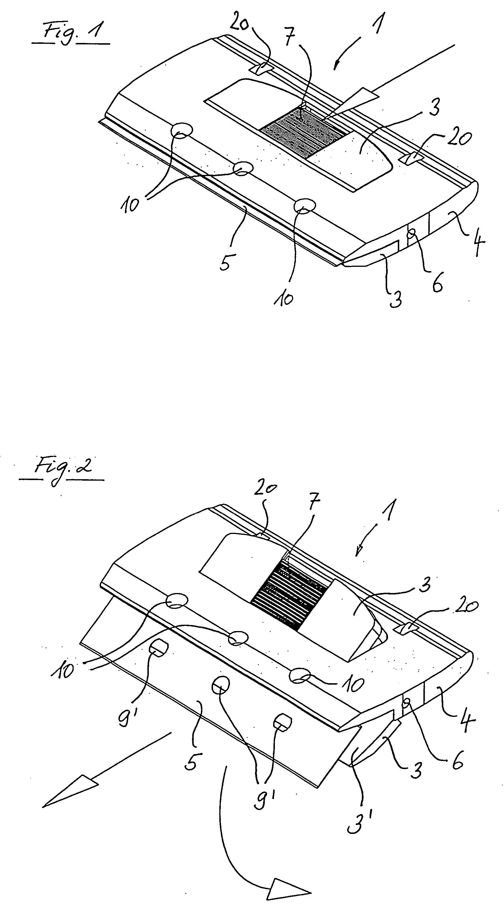
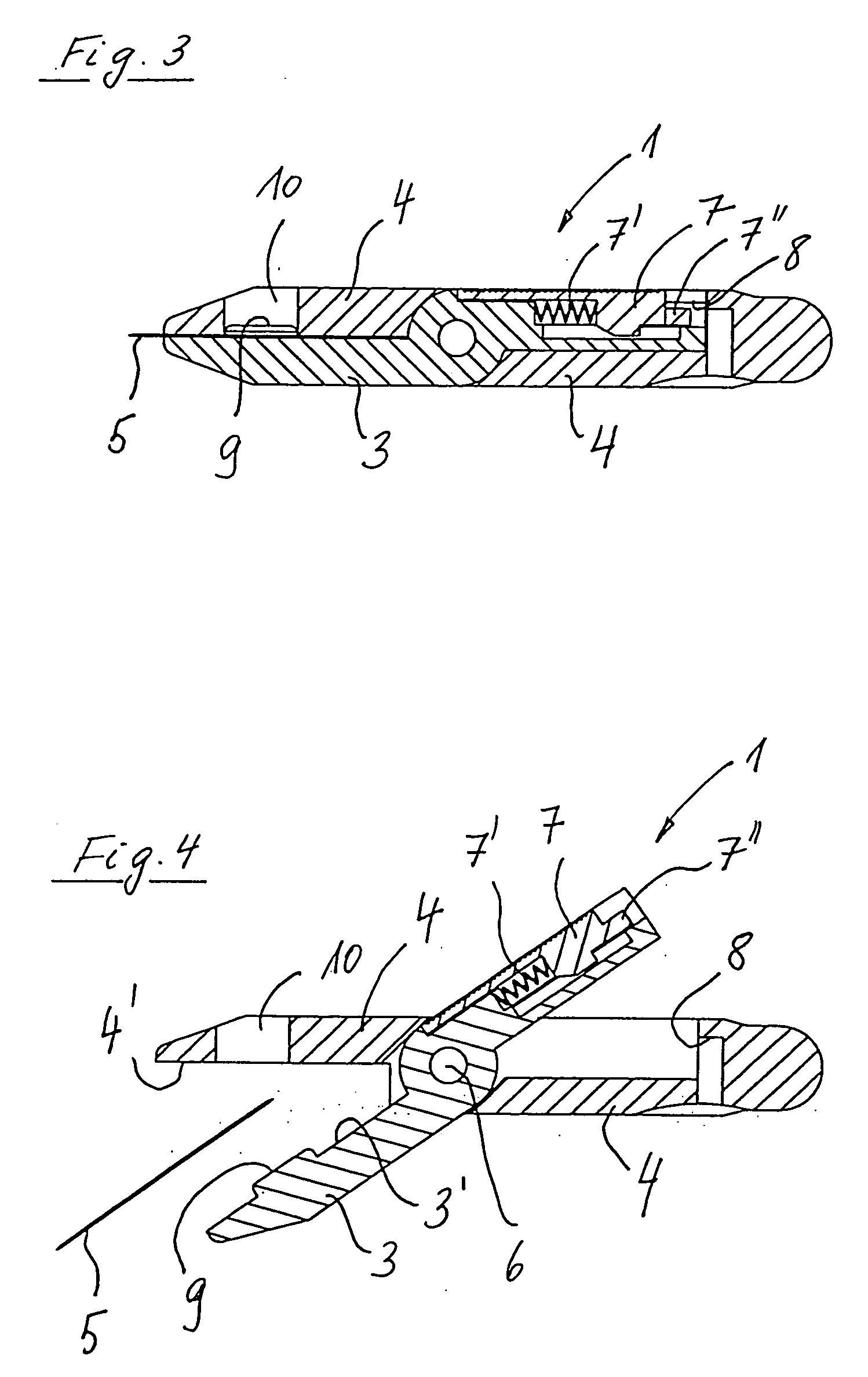
[0029] FIGS. 1 through 4 show schematic views of a preferred embodiment of the blade holder constituting the invention in isometric or cutaway presentation as well as in fastened and released condition.

[0030] The blade holder 1 shown serves releasable holding of a blade 5 and has a first section 3 and a second section 4 connected to each other in a scissors-like manner by means of an axial pin 6 so that they can be pivoted in relation to each other around the axis 6. The first section 3 has a first clamping surface 3' and the second section 4 has a second clamping surface 4' which are faced towards each other. As can be seen particularly in FIGS. 3 and 4, the pivoting axis, that is the axial pin 6, lies in the present embodiment example, essentially in the plane of the first clamping surface 3' and of second clamping surface 4' as well. In this way, the bla...


PUM


Abstract

The present invention relates to a blade holder (1) for releasable holding of a blade (5), in particular for cleaning purposes, having a first section (3) and a second section (4) connected to each other in such a way that they can be slewed with each other around an axis (6) and where the first section (3) has a first clamping surface (3') and the second section (4) has a second clamping surface (4') pointed towards each other and held against each other under tension by slewing the first (3) and/or the second (4) section in such a way that a blade (5) inserted between the clamping surfaces is held by the force of clamping and where the axis (6) essentially lies in the plane of the first (3') and/or the second (4') clamping surface and the first (3) and/or second (4) section in the tensioned condition of the clamping surfaces (3', 4') are held fast by means of a catch mechanism (7, 8). In this way, a blade holder is provided making possible enhanced safety in regard to cutting injuries when blades are changed.

Description

[0001] The present invention relates to a blade holder for releasable holding of a blade, in particular for cleaning purposes, in which a blade is held by means of a clamping force between the clamping surfaces of two sections of the blade holder.PRIOR ART[0002] Blade holders of the type cited above are used according to the prior art for various cleaning purposes, for example for removing coarse dirt residues from smooth surfaces such as windows and similar surfaces.[0003] Thus, German utility model DE 704 3159, for instance, discloses a scraper consisting of a holder with a U shaped cross-section simultaneously serving as a handle and a leaf-shaped blade squeezed between the mutually cushioning legs of the holder. The cutting edge of the blade can be covered by means of a cap attachable to the holder. The peculiarity of this blade holder consists in the fact that the blade holder is arranged so that it can be pivoted on the cover cap so that it can on the one hand be pivoted into ...

Claims


Application Information

Patent Timeline
IPC IPC(8): B26B5/00
CPCB26B5/00
Inventor SALMON, DIRK
Owner VERMOP SALMON
Why Eureka
Try Eureka