System for enhanced recovery of tangential energy from an axial pump in a loop reactor

a loop reactor and axial pump technology, applied in the field of slurry polymerization, can solve the problems of not being effective in converting tangential flow to axial flow, the elbow 104/b> to become packed with hardened polymer, etc., to achieve the effect of increasing the net axial flow velocity, increasing the useful work, and increasing efficiency

Inactive Publication Date: 2013-01-17
FLOWSERVE MANAGEMENT CO
View PDF6 Cites 2 Cited by
  • Summary
  • Abstract
  • Description
  • Claims
  • Application Information

AI Technical Summary

Benefits of technology

[0020]Conversion by the present invention of additional tangential flow into axial flow increases the net axial flow velocity. The additional pump head recovered will be proportional to the square of the net velocity increase. Thus, there will be an increase in useful work from the pump without a change in power consumption, yielding an increased efficiency.
[0021]Furthermore, quick recovery of the tangential fluid velocity into axial flow by the present invention decreases the friction of polymer particles on the reactor loop and pump sidewalls, thereby reducing the amount of polymer decay and increasing the percentage of useable and saleable product obtained from the reactor.

Problems solved by technology

Furthermore, upsets in polymerization systems sometimes cause the elbows 104 to become packed with hardened polymer.
If the vanes 302 were parallel to the pipe axis, they could have any width and spacing, but of course they would not be effective in converting tangential flow to axial flow.

Method used


Image

  • System for enhanced recovery of tangential energy from an axial pump in a loop reactor
  • System for enhanced recovery of tangential energy from an axial pump in a loop reactor
  • System for enhanced recovery of tangential energy from an axial pump in a loop reactor

Examples


Embodiment Construction

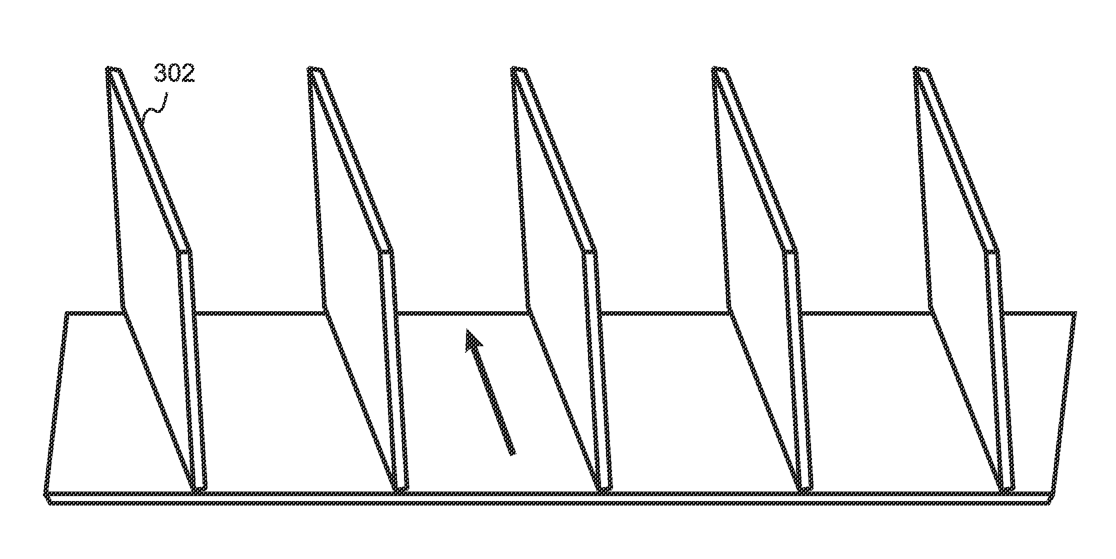
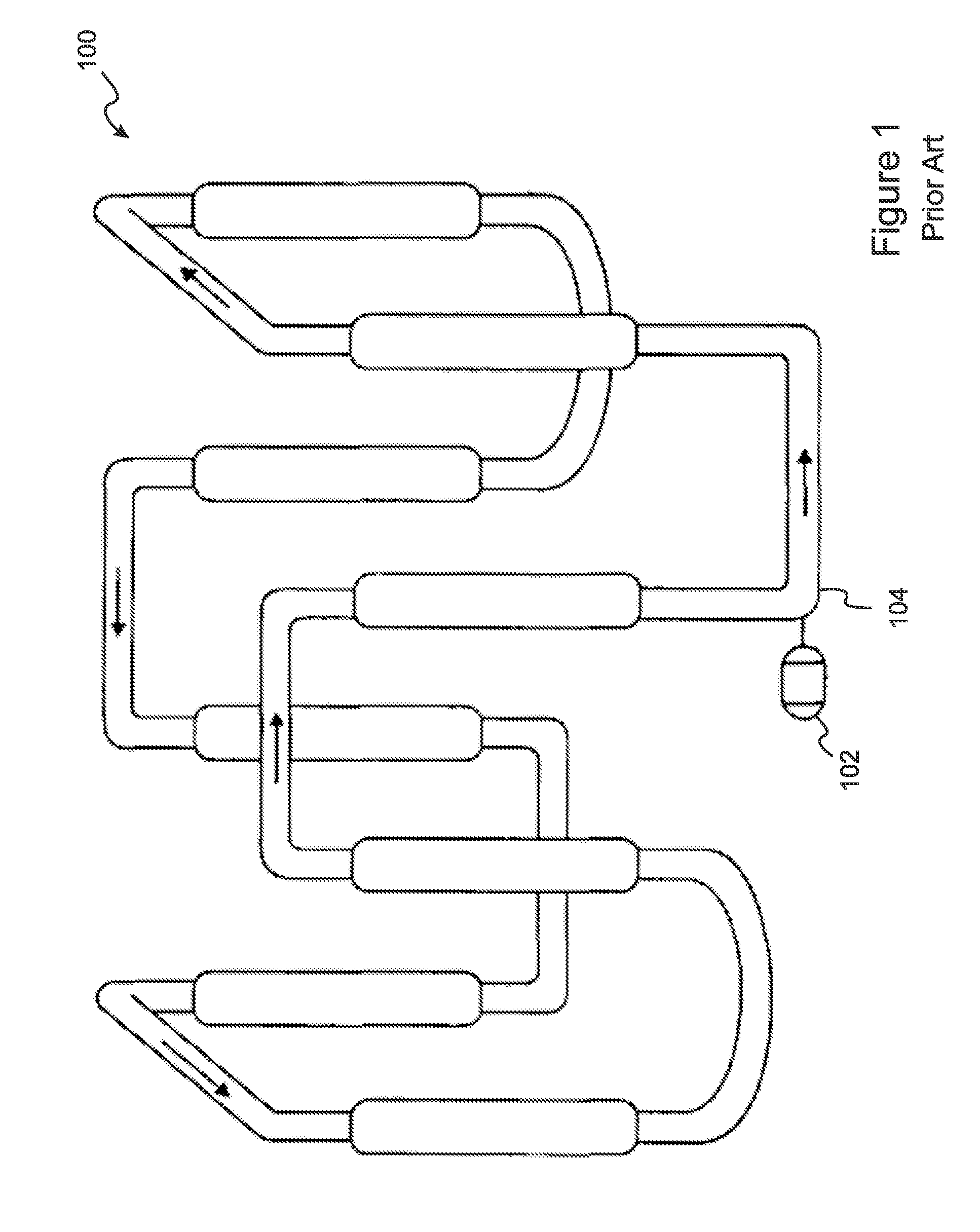
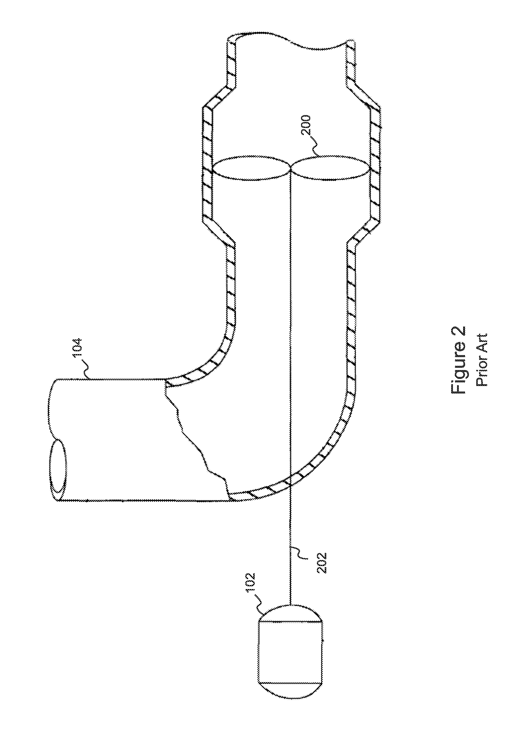
[0064]With reference to FIG. 7, an axial pumping system for a loop reactor includes an elbow section 104 and a separate, straight impeller section 700. An outlet end 706 of the impeller section 700 is attachable to an inlet end 702 of the elbow section. A guide vane assembly 704 is fixed within the impeller section 700 proximal to its outlet end 706. The elbow section 104 is penetrated by a pump shaft 202 which is coupled to a pump motor 102 at a proximal end of the pump shaft 202, the pump motor 102 being external to the elbow section 104. A distal end of the pump shaft 202 extends through a portion of the elbow section 104, out through the inlet end 702 of the elbow section 104, and into the impeller section 700 through an opening in the guide vane assembly 704.

[0065]An impeller 200 is attachable to the distal end of the pump shaft 202, so as to be located within the impeller section 700 proximal to an inlet end 708 of the impeller section 700. In the embodiment of FIG. 7, the len...


PUM


Abstract

A loop reactor axial pump system improves conversion of tangential to axial flow of a flowing slurry by attaching a straight impeller section to the inlet of an elbow section. A pump shaft extends rotatably from the elbow through guide vanes located in the impeller section, so that flow from an impeller mounted on the shaft passes through the guide vanes before entering the elbow. When the impeller section is detached, the guide vanes have “see through” access from both ends, thereby allowing the guide vanes to be longer and/or more curved than in the prior art. Guide vanes can be straight or curved, and can have inlet angles approximating the absolute flow angle of the fluid, and/or outlet angles approximating 0 degrees. Additional guide vanes can be included in the elbow. Additional straight pipe sections containing only guide vanes can be included between the impeller section and the elbow.

Description

RELATED APPLICATIONS[0001]This application claims the benefit of U.S. Provisional Application No. 61 / 508,210, filed Jul. 15, 2011, which is herein incorporated by reference in its entirety for all purposes.FIELD OF THE INVENTION[0002]The invention relates to slurry polymerization in a liquid medium, and more particularly, to pumping apparatus for a loop reactor used for slurry polymerization.BACKGROUND OF THE INVENTION[0003]Polyolefins such as polyethylene and polypropylene may be prepared by particle form polymerization, also referred to as slurry polymerization. With reference to FIG. 1, in this technique, feed materials such as monomer and catalyst are fed to a loop reactor 100, and a product slurry containing solid polyolefin particles in a liquid medium is taken off or withdrawn from the reactor 100.[0004]With reference to FIG. 2, in a loop polymerization operation, a fluid slurry is circulated around the loop reactor 100 using one or more pumps 102, typically axial flow pumps ...

Claims


Application Information

Patent Timeline
Patent Type & Authority Applications(United States)
IPC IPC(8): F03B11/02
CPCF04D29/548
Inventor ANDREWS, DALE B.
Owner FLOWSERVE MANAGEMENT CO
Why Eureka
Try Eureka