Systems and methods for implementing an open thermodynamic cycle for extracting energy from a gas

a technology of thermodynamic cycle and energy extraction, which is applied in the direction of mechanical equipment, non-fuel substance addition to fuel, machines/engines, etc., can solve the problems of limited amount of energy extracted, waste of thermal energy carried by exhaust gas, and inability to use thermal energy to produce useful work

Inactive Publication Date: 2015-04-30
OHIO STATE INNOVATION FOUND
View PDF27 Cites 3 Cited by
  • Summary
  • Abstract
  • Description
  • Claims
  • Application Information

AI Technical Summary

Benefits of technology

[0003]Systems and method for extracting energy from a gas are disclosed herein. In particular, systems and methods for implementing a series of thermodynamic transformations by means of which it is possible to extract useful work from a gas carrying thermal energy due its thermodynamic state are disclosed. An example system for extracting energy from a cycle gas can include an expander for expanding the cycle gas, a heat exchanger in fluid connection with the expander for cooling the expanded cycle gas while maintaining the expanded cycle gas at an approximately constant pressure and a compressor in fluid connection with the heat exchanger for compressing the cooled cycle gas. Optionally, the cycle gas can be expanded to a pressure less than ambient pressure, and the cooled cycle gas can be compressed to at least ambient pressure. Optionally, a pressure of the cycle gas before expansion is greater than ambient pressure.

Problems solved by technology

However, the thermal energy is not used to produce useful work.
Thus, the thermal energy carried by exhaust gas is wasted.
In some cases, the thermal energy is extract from exhaust gas but the amount of energy extracted has been limited.

Method used


Image

  • Systems and methods for implementing an open thermodynamic cycle for extracting energy from a gas
  • Systems and methods for implementing an open thermodynamic cycle for extracting energy from a gas
  • Systems and methods for implementing an open thermodynamic cycle for extracting energy from a gas

Examples


example calculations

[0044

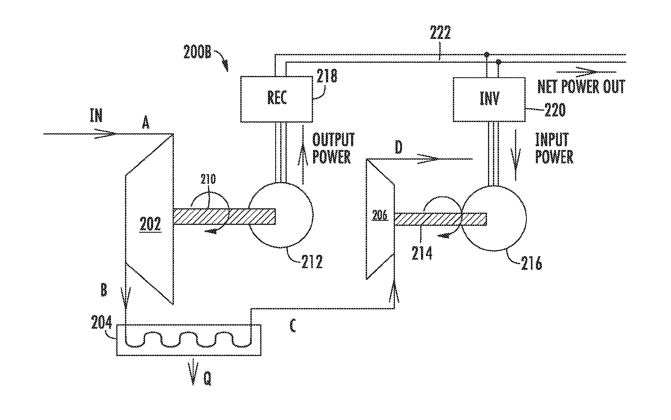
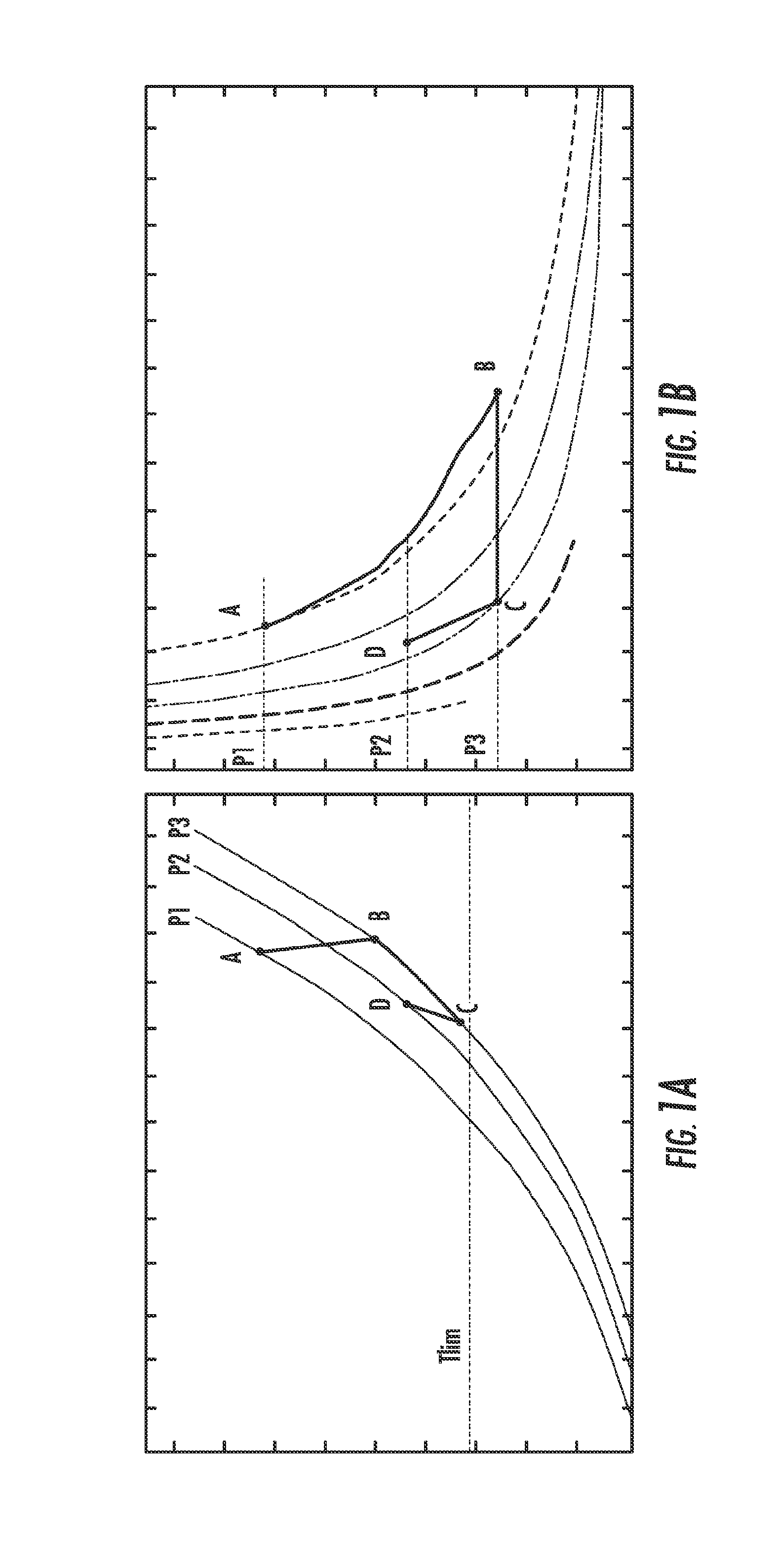
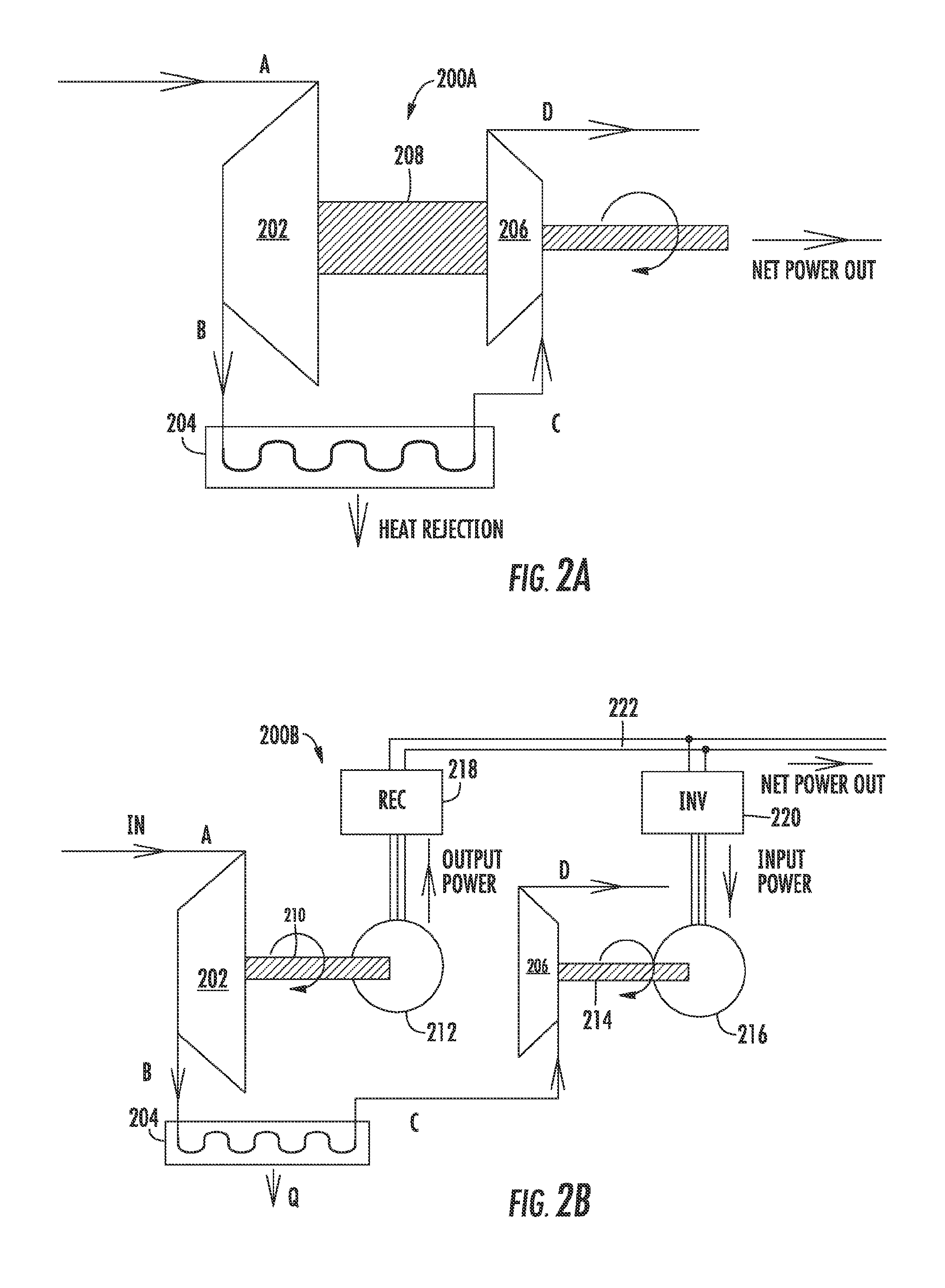
[0045]An example of a first principle thermodynamic calculation is presented below in order to demonstrate the advantages provided by the open thermodynamic cycle discussed herein. The calculation shows some representative metrics of the cycle, for instance, net output power and overall thermodynamic efficiency. In the calculation, the following assumptions are introduced: (1) the pressure and temperature at point A are known, as well as with the fluid mass flow rate; (2) the final pressure at point D (e.g., atmospheric pressure) is imposed; (3) the temperature at point C (e.g., representing the lower limit of the cycle) is known; (4) the working fluid is air, with temperature-dependent specific heats; and (5) the compression and expansion processes are adiabatic and irreversible, with constant isentropic efficiency. The calculations have been carried out using the software ENGINEERING EQUATION SOLVER (EES) of F-CHART SOFTWARE, MADISON, Wis. The assumptions and calculations are...


PUM


Abstract

Systems and method for extracting energy from a gas are disclosed herein. In particular, systems and methods for implementing a series of thermodynamic transformations by means of which it is possible to extract useful work from a gas carrying thermal energy due its thermodynamic state are disclosed. An example system for extracting energy from a cycle gas can include an expander for expanding the cycle gas, a heat exchanger in fluid connection with the expander for cooling the expanded cycle gas while maintaining the expanded cycle gas at an approximately constant pressure, and a compressor in fluid connection with the heat exchanger for compressing the cooled cycle gas.

Description

CROSS-REFERENCE TO RELATED APPLICATIONS[0001]This application claims the benefit of U.S. Provisional Patent Application No. 61 / 620,476, filed on Apr. 5, 2012, entitled “Open Thermodynamic Cycle for Waste Heat Recovery (3C Cycle),” and U.S. Provisional Patent Application No. 61 / 709,315, filed on Oct. 3, 2012, entitled “Application of the 3C Cycle to the EGR Loop of a Combustion Engine,” the disclosures of which are expressly incorporated herein by reference in their entireties.BACKGROUND[0002]Exhaust gas carries thermal energy due to its thermodynamic state. Exhaust gas can be a by-product of a number of devices or systems such as internal combustion engines, for instance, and is oftentimes discharged to the surrounding environment without recovering the thermal energy. Additionally, exhaust gas is recirculated from an exhaust manifold to an intake manifold of the internal combustion engine. However, the thermal energy is not used to produce useful work. Thus, the thermal energy carr...

Claims


Application Information

Patent Timeline
Patent Type & Authority Applications(United States)
IPC IPC(8): F01N5/02F02B37/00F02M25/07
CPCF01N5/02F02B37/005F02M25/0726F02M25/0706F02B37/00F02M26/04F02M26/05F02M26/22F02M26/28F02M26/34Y02T10/12
Inventor CANTEMIR, CODRIN-GRUIECHIARA, FABIOCANOVA, MARCELLO
Owner OHIO STATE INNOVATION FOUND
Why Eureka
Try Eureka