
Windmill apparatuses and methods of mounting blades to enhance their performance

a technology of windmills and blades, which is applied in the direction of wind turbines, propulsion parts, machines/engines, etc., can solve the problems of not being able to meet the needs of air tanks, not being able to run cars or trucks on compressed air, and not being able to meet the weight requirements of air tanks. achieve the effect of useful work

Inactive Publication Date: 2007-09-11
MCCABE FRANCIS J
View PDF18 Cites 5 Cited by
  • Summary
  • Abstract
  • Description
  • Claims
  • Application Information

AI Technical Summary

Benefits of technology

[0015]This is an improved airfoil arrangement which can provide airfoils in combination which provides needed structural strength while causing (windmill) lift; (propeller) thrust; (fan) flow enhancement which is greater than the sum of the individual air flows (in the same air flow conditions).

Problems solved by technology

Despite extensive knowledge of the desirability of such vehicles, there is not currently on the market for mass production and delivery to the general public any such device.
Attempts to run cars or trucks on compressed air have foundered on the weight of the air tanks needed to obtain a minimally acceptable range of 100 miles or more.
Engineers who have looked at hybrid-powered vehicles have felt that compressed air compared unfavorably with batteries as a medium for storing energy and were inherently inefficient.
One of the problems that I have noted in my work with windmills is that there may be periods when the wind is either very slow or very fast for a sustained period of time.

Method used


Image

  • Windmill apparatuses and methods of mounting blades to enhance their performance
  • Windmill apparatuses and methods of mounting blades to enhance their performance
  • Windmill apparatuses and methods of mounting blades to enhance their performance

Examples


Embodiment Construction

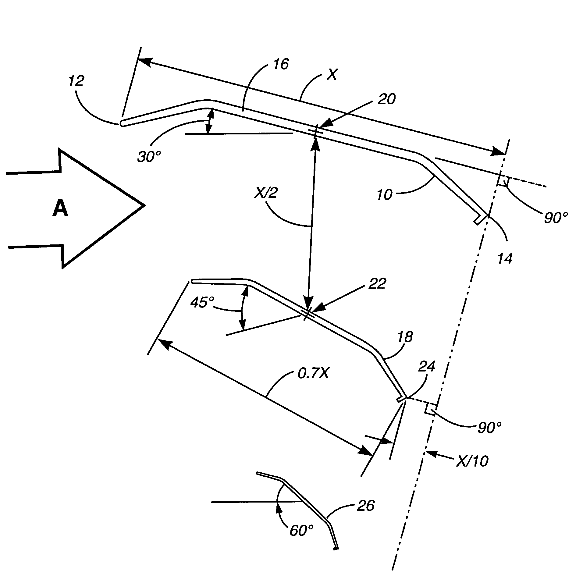
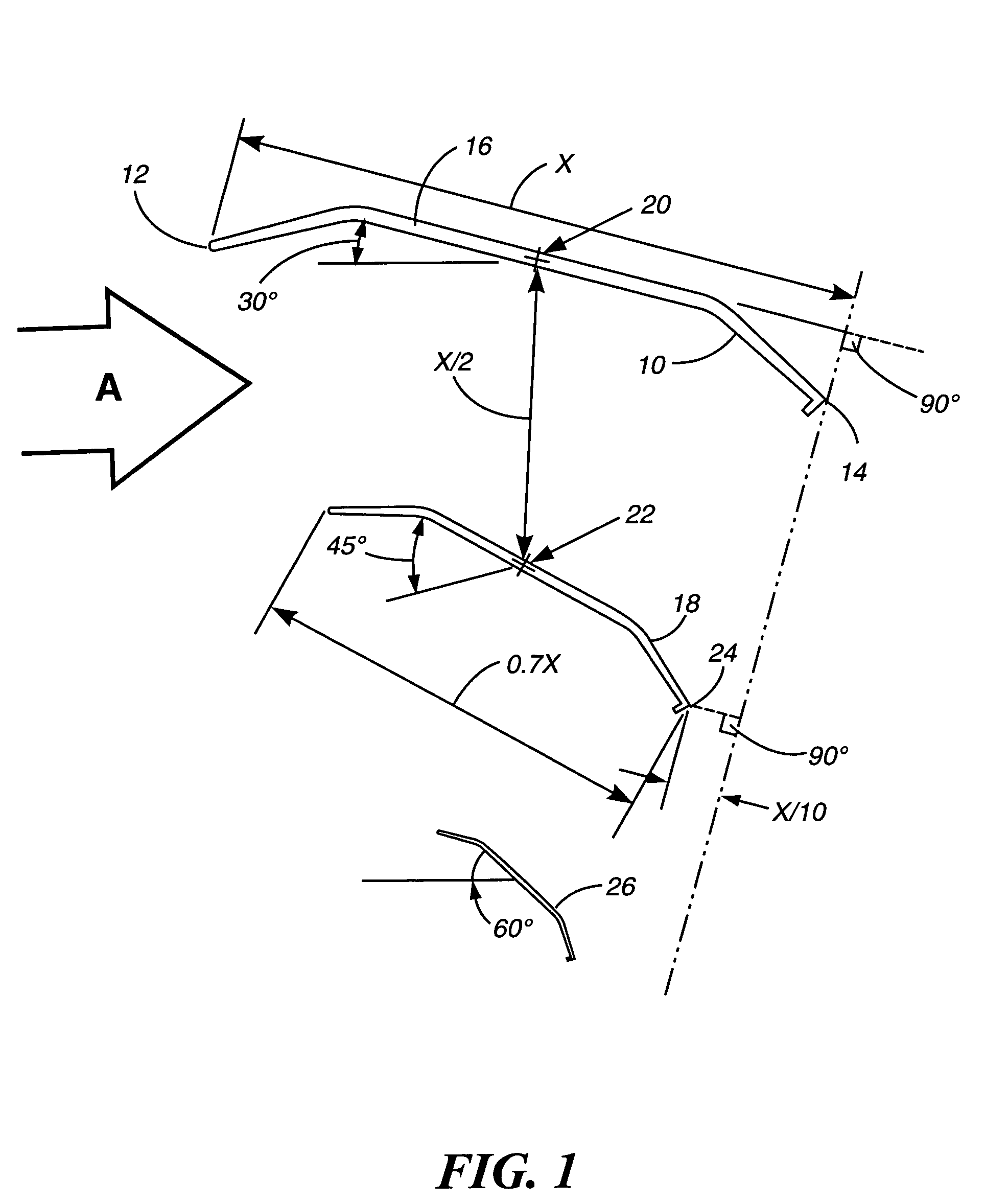
[0051]Referring to FIG. 1, this shows graphically an end view representation of a plurality of air foils or blades positioned with respect to one another and the entry air flow, as shown by the arrow “A”. The blades are shown as being predominantly flat, of uniform cross-section and having a lip at the down wind edge (as shown in my prior U.S. patents for air foils and windmill structures such as U.S. Pat. No. 6,132,181, issued Oct. 17, 2000). The blade 10 has a cord length “X” measured from the leading edge tip 12 to tip 14 on a line parallel to the plane of the central portion 16. Blade 18 is most preferably somewhat smaller in overall length. The blades are positioned with respect to one another such that the center 20 of the central portion 16 of the blade 10 is spaced approximately 50% of the blade cord length “X”, that is, X divided by 2, from the center 20 to the center 22 of the central portion of the blade 18.

[0052]The lower blade 18 is positioned with respect to the upper ...


PUM


Abstract

A windmill apparatus has multiple pairs of blades to enhance power output and lift performance. The apparatus has multiple double acting piston / cylinders actuated by the windmill, which includes several clutches that are used to engage and disengage the windmill from the motor.

Description

CROSS-REFERENCE TO RELATED APPLICATIONS[0001]This application is a Continuation-in-Part of my prior applications, namely AIR PROPULSION APPARATUS WITH WINDMILL HAVING MULTIPLE WINDMILL BLADES TO ENHANCE PERFORMANCE, Ser. No. 10 / 026,334, filed Dec. 21, 2001 now abandoned and the disclosures of the applications cross referenced therein, namely, AIR PROPULSION DEVICES, Ser. No. 60 / 258,957, filed Dec. 29, 2000; WINDMILL WITH MULTIPLE DOUBLE-ACTING PISTON / CYLINDER COMPRESSOR SYSTEM AND APPARATUS AND METHOD OF MOUNTING MULTIPLE WINDMILL BLADES TO ENHANCE PERFORMANCE, Ser. No. 09 / 990,855, filed Nov. 21, 2001 now abandoned; and includes the applications referenced therein, namely, WINDMILL WITH TWO PISTON COMPRESSOR SYSTEM, Ser. No. 60 / 252,772, filed Nov. 22, 2000; and APPARATUS AND METHOD OF MOUNTING MULTIPLE BLADES TO ENHANCE PERFORMANCE, Ser. No. 60 / 252,812, filed Nov. 22, 2000; the disclosures of all of which are incorporated herein by reference as if fully set forth.BACKGROUND OF THE I...

Claims


Application Information

Patent Timeline
Patent Type & Authority Patents(United States)
IPC IPC(8): F03D11/04B62D57/00F03D1/00F03D9/00F04B17/02
CPCF03D1/00F03D9/001F04B17/02Y02E10/72F03D9/28B60K16/00F03D1/025F03D9/32
Inventor MCCABE, FRANCIS J.
Owner MCCABE FRANCIS J
Learn More