Method and apparatus for performing data flow ingress/egress admission control in a provider network

a data flow and provider network technology, applied in the field of method and apparatus for performing data flow ingress/egress admission control in a provider network, can solve the problems of network utilization inefficiencies, inefficiency in utilization of circuit switched network capacity, and limited flexibility of circuit switched connection

Active Publication Date: 2004-08-12
CIENA
View PDF5 Cites 381 Cited by
  • Summary
  • Abstract
  • Description
  • Claims
  • Application Information

AI Technical Summary

Problems solved by technology

While new packet switching technologies continue to emerge, service providers must continue to service older technologies as it takes many years for end users to phase out a particular technology.
But these circuit switched connections are limited in flexibility: they are available in limited bandwidth sizes: 10 Gbps, 2.5 Gbps, 622 Mbps, 155 Mbps, 53 Mbps, 1.5 Mbps, 64 Kbps, and are provisioned and maintained independently of the packet switched traffic.
The static nature of these circuit connections imposes inefficiency in utilization of the capacity of the circuit switched network when carrying packet data traffic.
As a result, the interface between the packet data layer (layer 2) of the carrier network and the circuit switch layer (layer 1) leads to network utilization inefficiencies and difficult and expensive provisioning and maintenance tasks for the service providers.
A serious drawback with the draft-martini design is that communication carriers must rely on MPLS / IP backbones with expensive high-performance routers to support the control messaging and label distribution protocol thereby greatly increasing the cost of transporting Layer-2 traffic which is otherwise inexpensive and relatively simple.
However, there are a number of issues in the UNI approach:
Both user and network elements must implement the UNI specification thereby dramatically increasing the cost of implementation and creating compatibility problems with non-UNI networks that interface with the UNI-enabled network.
This approach can potentially introduce user traffic aggregation from optical network edges.
Also, this approach may require the carriers to reveal internal routing and resource information to the external customers, which is not practical in most of the operational networks today.

Method used


Image

  • Method and apparatus for performing data flow ingress/egress admission control in a provider network
  • Method and apparatus for performing data flow ingress/egress admission control in a provider network
  • Method and apparatus for performing data flow ingress/egress admission control in a provider network

Examples


embodiment 1

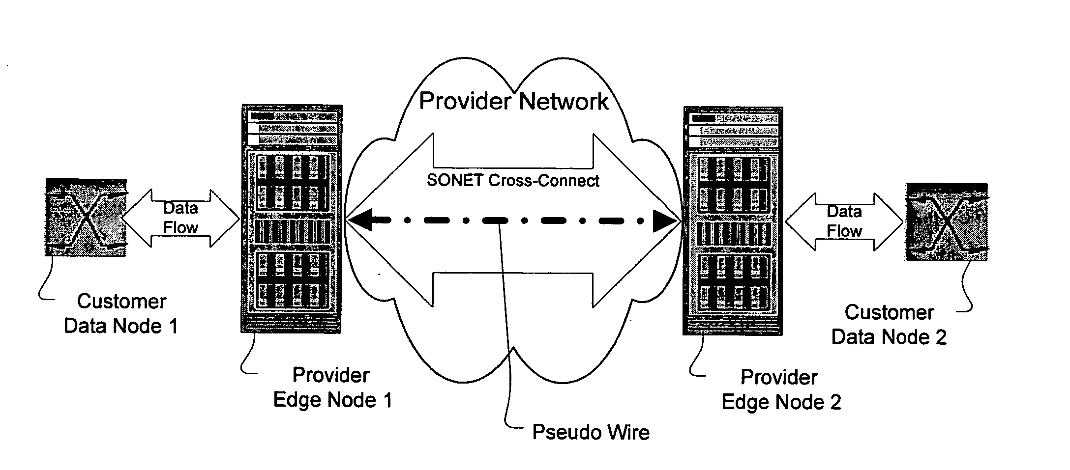
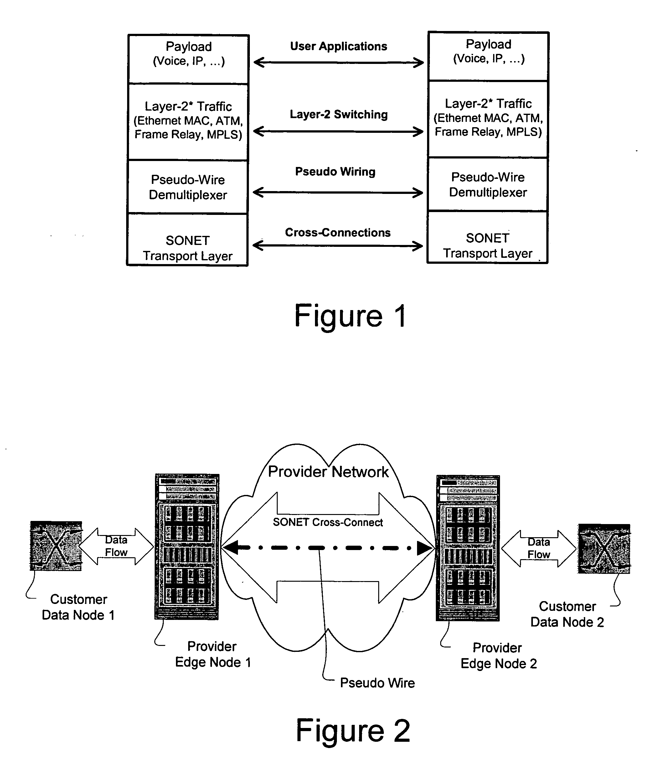
[0290] Provider Edge Nodes C and H use signaling protocols, such as those described above in relation to embodiment 1 or by using LDP and draft-martini, to provision pseudo-wires. The result of the provisioning is to aggregate multiple data flows into a single data tunnel. Each data flow is represented as a pseudo-wire within the data tunnel as will be described in more detail below in relation to FIG. 31.

[0291] In addition to the pseudo-wire information that has been described above in the first embodiment, the second embodiment requires the provider edge nodes to exchange the following information for each data flow (or pseudo-wire):

[0292] CIR (Committed Information Rate): This information describes the amount of bandwidth that is required for a given pseudo-wire. This CIR information is essentially the same, in and of itself, as the CIR traditionally used in Frame Relay service offerings but is utilized by the invention in a completely different context and environment. CIR is de...

first embodiment

[0303] To interface with the provider backbone, one or multiple provider-interface line modules (not shown) should be provided as is known in the art. Such provider-interface line modules interface with the Packet-Access Line Modules 210 to inject packets into provider's backbone in the conventional fashion. Depending on the type of provider's network, they can be a conventional router packet forwarding module, a Layer-2 switching module, or a TDM switching module (see first embodiment above for an example).

[0304] Using or otherwise accessing the control module 200, network operators request the setup of pseudo-wires. The actual details of pseudo-wire setup have been exemplified and specified in other relevant documents [draft-martini, LDP] a significant variation of which is described above in relation to embodiment one. To support the second embodiment, the pseudo-wire process needs to maintain the following additional information within the databases shown in FIG. 24:

[0305] Sessi...

second embodiment

[0357] Operation Of Second Embodiment

[0358] The following sections describe the methods and operations of the second embodiment. These methods may be performed utilizing the elements described above or their equivalents.

[0359] Provisioning Pseudo Wires for Admission Control

[0360] This section describes the inventive method of provisioning pseudo-wires that permit admission control functionality. Following sections will describe both pseudo-wire shuffling and preemption according to the inventive concepts.

[0361] The provisioning of pseudo wires that will permit admission control functionality to operate is a process that includes the exchanging of specific resource information between PE nodes during the creation of pseudo-wires.

[0362] Setting up pseudo-wires (PW) may follow a procedure as defined in [PWE3-CTRL] or the procedure as defined above in the first embodiment. The second embodiment, however, modifies these provisioning processes to operate in context of and to otherwise per...


PUM


Abstract

A method, apparatus and network for transporting layer-2 frames, such as Ethernet MAC, ATM AAL5, and Frame Relay, over MPLS, SONET/SDH, or OTN optical transport networks as well as electrical transport networks is disclosed. The method establishes "pseudo-wires" between, for example, routers, Layer-2 packet switches, or SONET/SDH switches. Inter-related ingress and egress resource tables may be used by provider edge nodes to negotiate consistently managed data tunnels across a provider network on behalf of data flowing from/to a diverse base of customer edge nodes. Detailed network resource information particular to each of the data flows is exchanged between provider edge nodes during the creation of pseudo-wires. Admission control algorithms are applied at the ingress and egress points in order to manage the data flows into a provider network and exiting from a provider network to customer equipment. By applying pseudo-wire shuffling and preemption techniques, the providers can make better use of their network resources by admitting more pseudo-wires.

Description

[0001] This application claims priority to U.S. patent application Ser. No. 10 / 757,528, filed Jan. 15, 2004 (which is a provisional conversion of and claims priority to Provisional Application No. 60 / 440,313, filed Jan. 15, 2003); U.S. Provisional Patent Application 60 / 444,456, filed Feb. 3, 2003, and U.S. Provisional Patent Application 60 / 444,440, filed Feb. 3, 2003, all of which are by common inventors, Ping Pan and Ralph Theodore Hofmeister, all of which are hereby fully incorporated herein by reference.[0002] 1. Field of Invention[0003] The invention generally relates to methods and apparatuses for transporting diverse traffic types such as different types of layer-2 traffic over an optical transport network such as a SONET / SDH network. The invention more particularly relates to utilizing pseudo-wires carried directly on top of the SONET, SDH, or OTN layer to transport diverse data packet traffic types such as various types of layer-2 traffic. The second embodiment of the invent...

Claims


Application Information

Patent Timeline
Patent Type & Authority Applications(United States)
IPC IPC(8): H04L12/46H04L12/56
CPCH04L12/4633H04L49/103H04L49/602H04L49/253H04L49/205
Inventor HOFMEISTER, RALPH THEODOREPAN, PING
Owner CIENA
Why Eureka
Try Eureka