Garment hanger

a technology for hanging clothes and clothes, applied in the field of garment hangers, can solve the problem that clothes hanging on a conventional garment hanger easily fall off,

Inactive Publication Date: 2004-08-19
HUANG CHEN HUNG
View PDF5 Cites 16 Cited by
  • Summary
  • Abstract
  • Description
  • Claims
  • Application Information

AI Technical Summary

Benefits of technology

0008] In order to achieve the above and other objectives, a garment hanger of the invention includes a hanger body, a clasp and at least one engaging element. The hanger body has a plurality of first rounded teeth that are formed respectively along sides thereof with a constant clearance between two adjacent teeth. Each of the first rounded teeth has a top larger than its bottom to form a small mouth between the tops of two adjacent teeth. A hooked neck is connected to a roof of the hanger body. A pair of round notches is respectively disposed on exterior edges of a hook portion of the hooked neck in a symmetrical manner. The clasp has a protruding button and a tab at opposite ends. The protruding button and the tab respectively engage with the notches of the hooked neck. The engaging element has second rounded teeth properly spaced on one side thereof to fit respectively in clearances formed by the adjacent first teeth.

Problems solved by technology

A garment hung on a conventional garment hanger easily falls off due to to winding or excessive weight.

Method used


Image

  • Garment hanger
  • Garment hanger
  • Garment hanger

Examples


Embodiment Construction

[0021] Wherever possible in the following description, like reference numerals will refer to like elements and parts unless otherwise illustrated.

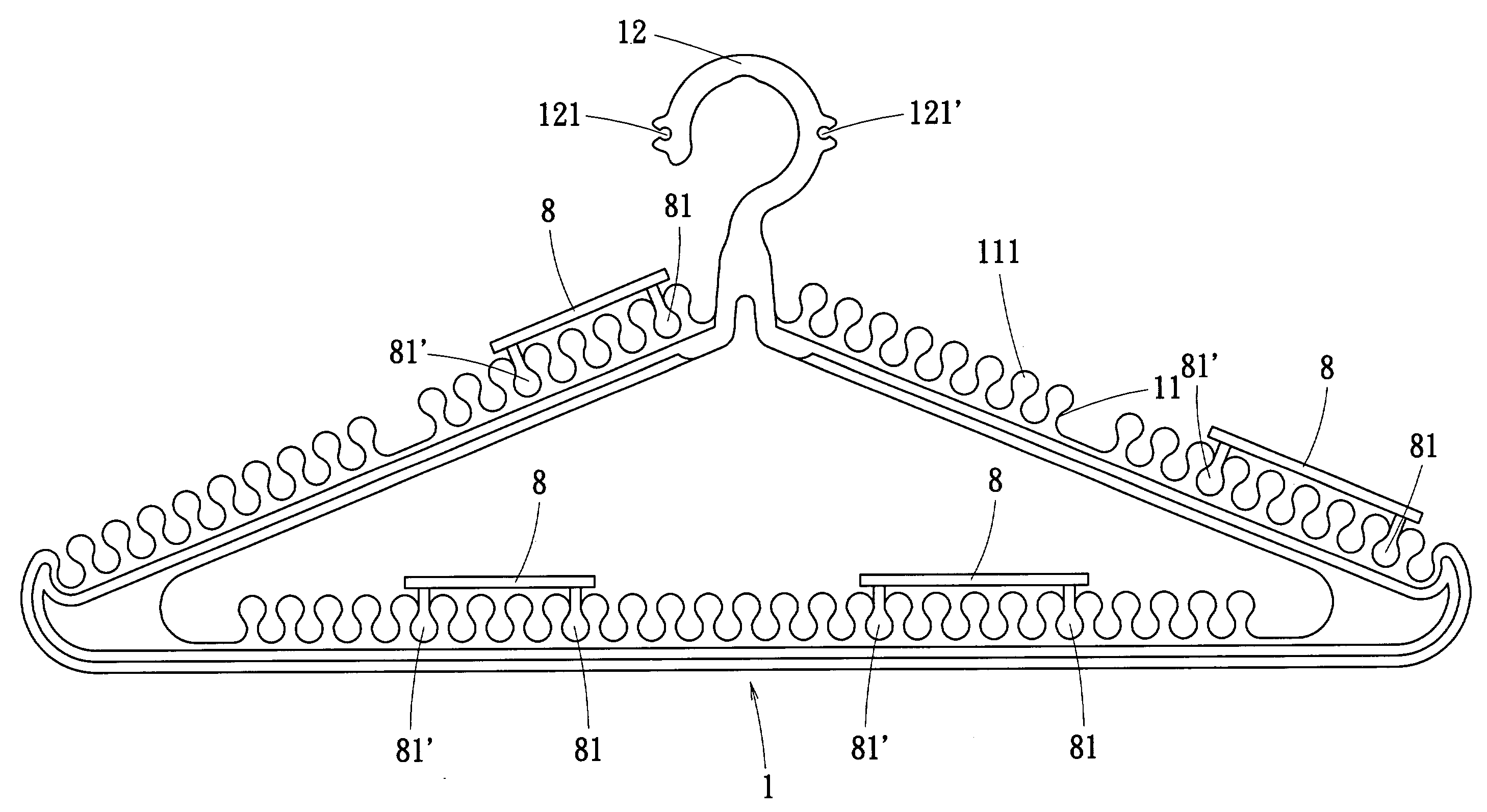
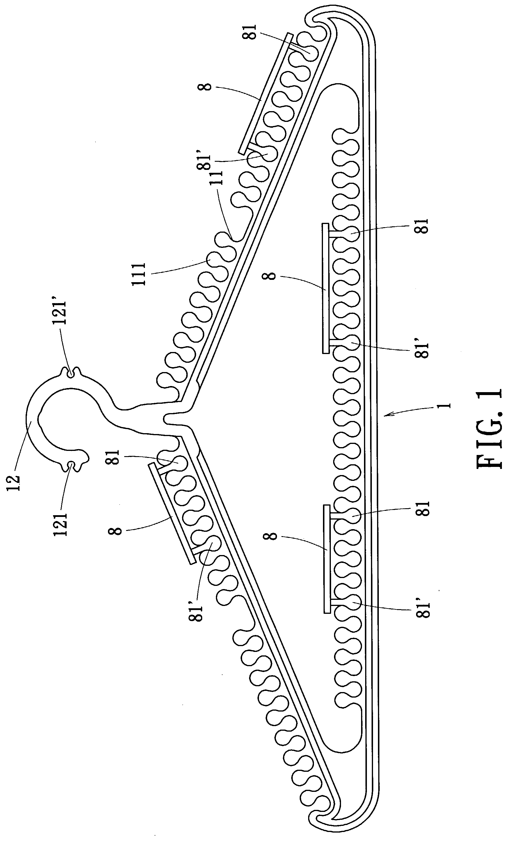
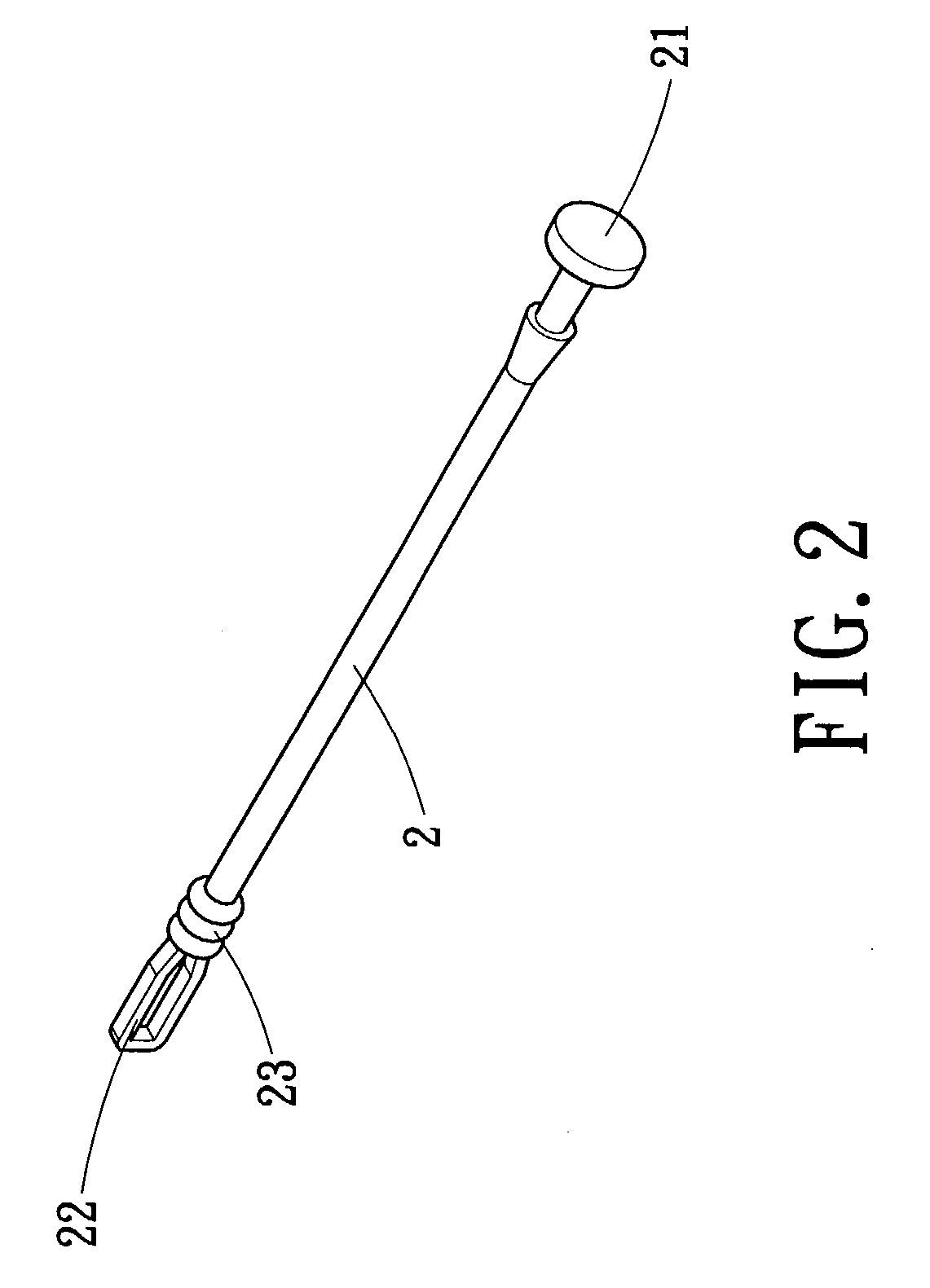
[0022] FIG. 1 is a schematic view of a garment hanger assembled with engaging elements according to one embodiment of the invention. FIG. 2 is a perspective view of a clasp that is used in a garment hanger according to one embodiment of the invention. The garment hanger of the invention includes a hanger body 1, a clasp 2, and at least one engaging element 8.

[0023] The hanger body 1 is made of, for example, plastic. The hanger body 1 is made by, for example, injection molding. The hanger body 1 is of triangular shape. First rounded teeth 11 are formed respectively along exterior surfaces of the sloped sides of the triangular hanger body 1, with a constant clearance between adjacent teeth 11. The first teeth 11 can be further formed on a bottom side of the hanger body 1. Each of the first rounded teeth has a top 111 larger than its bottom t...


PUM


Abstract

A garment hanger has a hanger body, a clasp and at least one engaging element. The hanger body has a plurality of first rounded teeth formed respectively along sides thereof, with a constant clearance between adjacent teeth. Each of the first rounded teeth has a top larger than its bottom to form a small mouth between the tops of two adjacent teeth. A hooked neck is connected to a roof of the hanger body. A pair of round notches is respectively disposed on exterior edges of a hook portion of the hooked neck in a symmetrical manner. The clasp has a protruding button and a tab at opposite ends. The protruding button and the tab respectively engage with the notches of the hooked neck. The engaging element has second rounded teeth properly spaced on one side thereof to respectively fit in clearances formed by the adjacent first teeth.

Description

[0001] 1. Field of the Invention[0002] The invention relates to a garment hanger and, more particularly, to a garment hanger having teeth on sides of a hanger body to fasten an item onto the hanger body.[0003] 2. Description of the Related Art[0004] A garment hung on a conventional garment hanger easily falls off due to to winding or excessive weight. A clip is usually used to further fasten the garment onto the garment hanger. In addition, the traditional garment hanger may further drop from a rod on which hangs.[0005] It is an object of the invention to provide a garment hanger having a plastic injection-molded hanger body with teeth spaced thereon, that allows a garment, such as underwear, tank tops, wide-neckline T-shirts and trousers, to be firmly fastened on the garment hanger without the need of clips. The garment hanger can be also properly positioned on the rod.[0006] It is another object of the invention to provide a garment hanger that can be firmly positioned on rods of ...

Claims


Application Information

Patent Timeline
Patent Type & Authority Applications(United States)
IPC IPC(8): A47G25/32A47G25/50A47G25/74
CPCA47G25/32A47G2025/1492A47G25/743A47G25/50
Inventor HUANG, CHEN HUNG
Owner HUANG CHEN HUNG
Why Eureka
Try Eureka