Air assisted spray nozzle assembly for spraying viscous liquids

a technology of air-assist spray nozzle and viscous liquid, which is applied in the direction of spray nozzle, spray apparatus, liquid spraying apparatus, etc., can solve the problems of affecting the efficiency of processing system, preventing the necessary uniform application of coating materials, and impede the discharge of liquid and air flow streams, so as to achieve the effect of more efficient spraying of highly viscous materials

Inactive Publication Date: 2004-08-19
SPRAYING SYST
View PDF5 Cites 25 Cited by
  • Summary
  • Abstract
  • Description
  • Claims
  • Application Information

AI Technical Summary

Benefits of technology

[0004] It is an object of the present invention to provide an improved air assisted spray nozzle assembly adapted for more efficiently spraying highly viscous materials.
[0005] Another object is to provide a spray nozzle assembly as characterized above which has a design which substantially reduces or eliminates undesirable build up of sprayed material on externally exposed faces of the liquid spray tip and air cap.
[0006] A further object is to provide a spray nozzle assembly of the above kind that is relatively simple in construction and which lends itself to economical manufacture and usage.

Problems solved by technology

By virtue of the turbulence that can be created as a result of the intermixing pressurized liquid and air streams discharging from the spray nozzle assembly, randomly directed particles can contact and accumulated on externally exposed faces of the liquid spray tip and air cap, which can quickly impede the discharge of the liquid and air flow streams and prevent the necessary uniform application of the coating materials.
Repeated interruption in the spray operation significantly affects efficiency of the processing system.

Method used


Image

  • Air assisted spray nozzle assembly for spraying viscous liquids
  • Air assisted spray nozzle assembly for spraying viscous liquids

Examples


Embodiment Construction

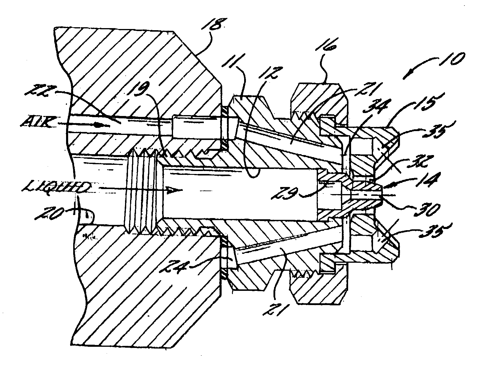
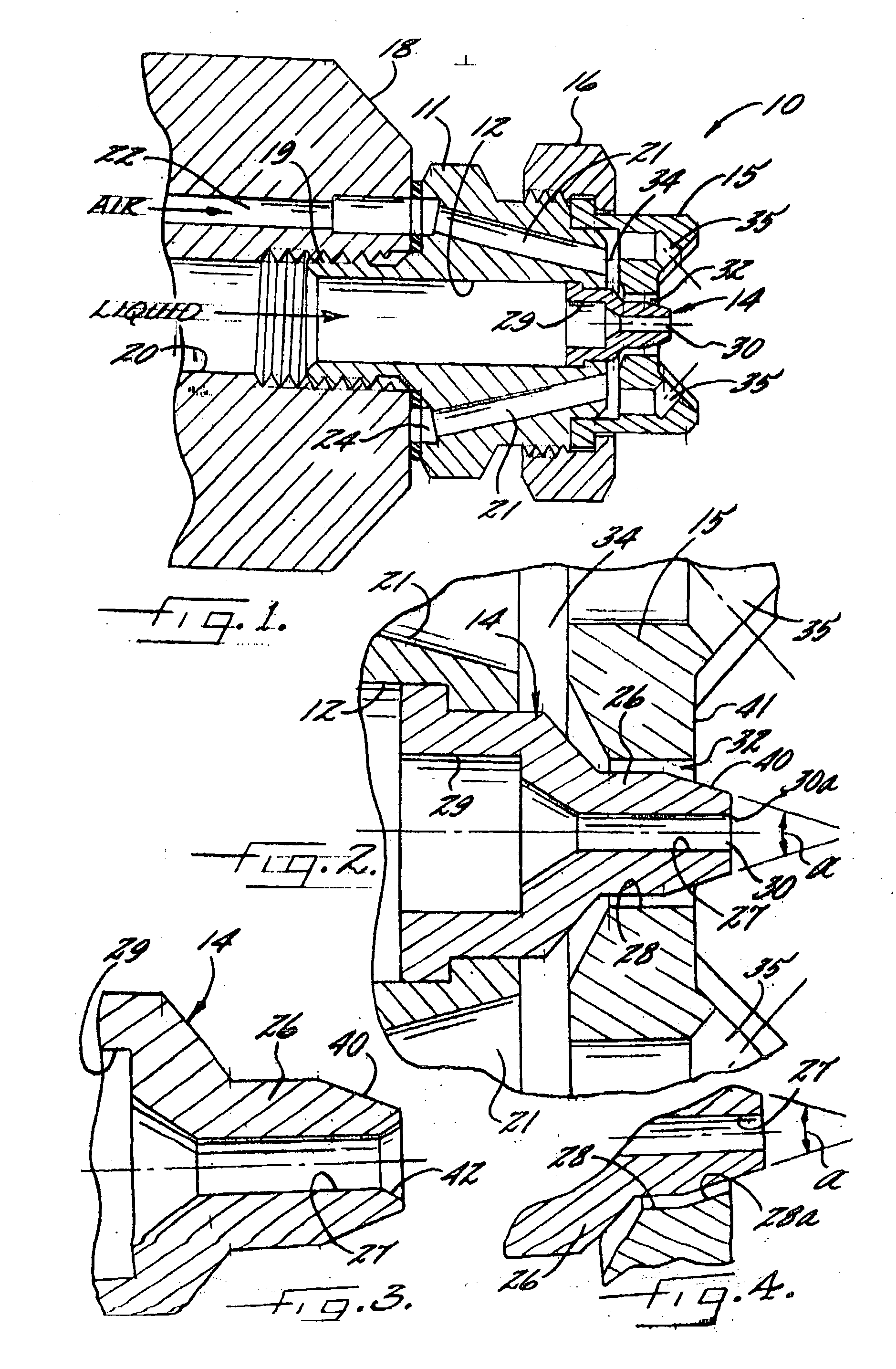
[0014] Referring now more particularly to FIG. 1 of the drawings, there is shown an illustrative external mix spray nozzle assembly 10 in accordance with the invention. The spray nozzle assembly 10 includes a nozzle body 11 having a central liquid flow passage 12 with a liquid spray tip 14 at the discharge end thereof and an air cap 15 mounted in surrounding relation to the discharge end of the nozzle body 11 by a retaining ring 16. The nozzle body 11 in this instance is affixed to the forward end of a base portion 18 by a threaded stem 19 with a central liquid passageway 20 of the base portion 18 communicating with the nozzle body passage 12. The nozzle body 11 further is formed with one or more pressurized air passages 21 which extend through the nozzle body 11 and which communicate with an air passage 22 in the base portions 18 through an annular chamber 24 in the upstream end of the nozzle body 11. In a known manner, suitable supply lines can be coupled to the base portion liqui...


PUM


Abstract

An external mix air atomizing spray nozzle assembly having a nozzle body formed with liquid and air passages, a spray tip at a downstream end of the nozzle body having a nose portion that defines a liquid discharge orifice, and an air cap mounted in surrounding relation to the spray tip nose portion. The air cap defines an annular pressurized air orifice about the spray tip nose portion and a plurality of angled air passages disposed radially outwardly thereof. Pursuant to the invention, the spray tip nose portion has a frustoconical end tapering inwardly in a downstream direction which enhances air entrainment and minimizes liquid turbulence in a zone immediately in front of the air cap and around the spray tip nose portion to prevent undesirable build up of spray material on the exposed end surfaces of the spray tip nose portion and air cap.

Description

[0001] The present invention relates generally to spray nozzle assemblies, and more particularly, to external mix air atomizing spray nozzle assemblies in which a discharging liquid flow stream is atomized and formed into the desired spray pattern by pressurized air externally of the liquid discharge orifice.[0002] External mix air atomizing spray nozzles are known for their ability to control liquid particle size and spray distribution by pressurized air, substantially independent of liquid flow rate. Such spray nozzle assemblies typically include a liquid spray tip through which the liquid flow stream is directed and an air cap mounted in surrounding relation to the liquid spray tip for directing pressurized air streams that interact with the liquid flow stream discharging from the spray tip to further break down the liquid into particles and to direct the particles into the desired spray pattern. Such air assisted spray nozzles commonly are used in industry for directing highly v...

Claims


Application Information

Patent Timeline
Patent Type & Authority Applications(United States)
IPC IPC(8): B05B7/06B05B7/08
CPCB05B7/0815B05B7/066
Inventor KOMORNICKI, WACLAW
Owner SPRAYING SYST
Why Eureka
Try Eureka