Transmission method and radio apparatus utilizing the transmission method
a technology of radio equipment and transmission method, which is applied in the direction of polarisation/directional diversity, wireless commuication services, and eavesdropping prevention circuits, etc., can solve the problem of breaching the security of information contained in radio signals
- Summary
- Abstract
- Description
- Claims
- Application Information
AI Technical Summary
Problems solved by technology
Method used
Image
Examples
first embodiment
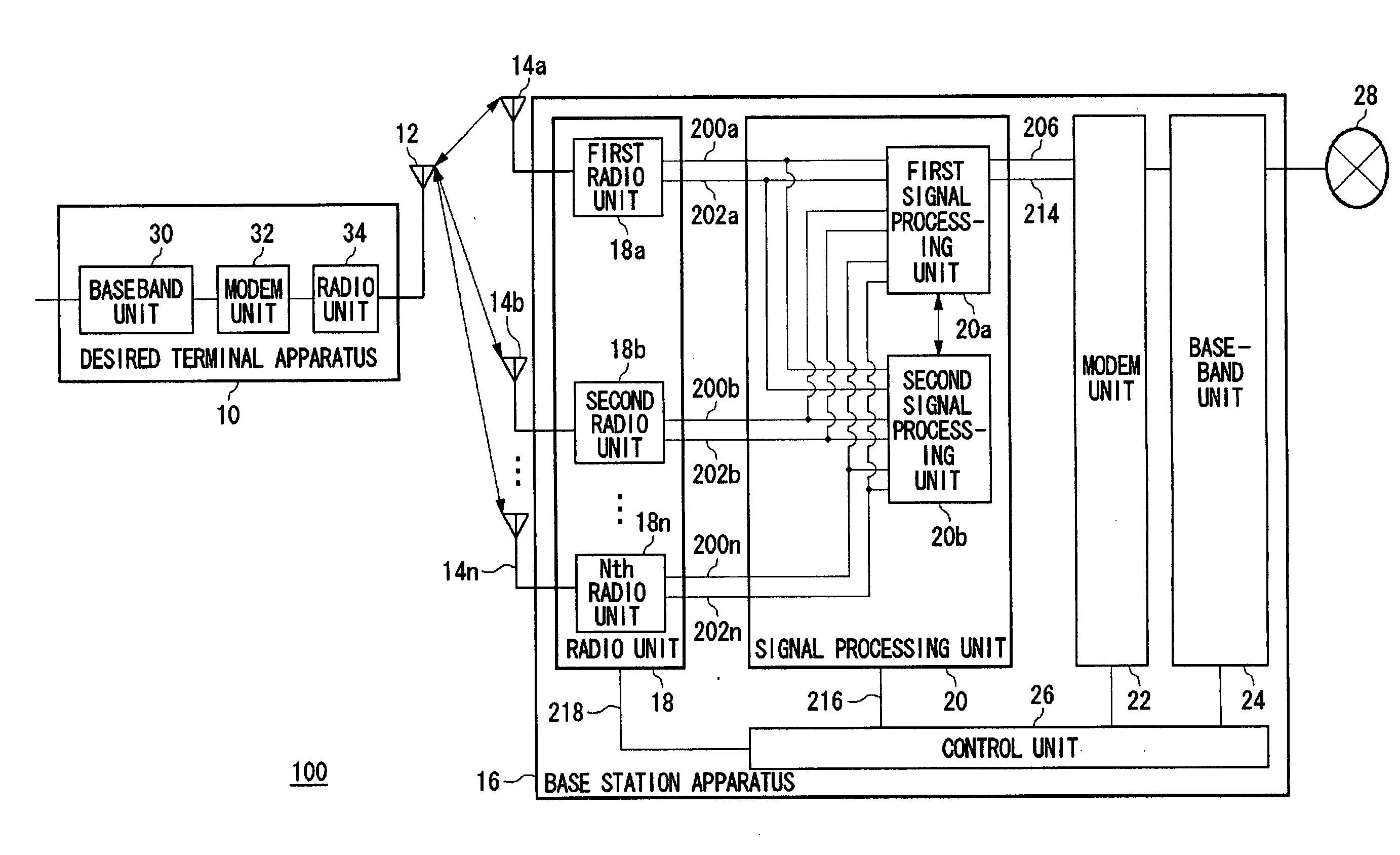
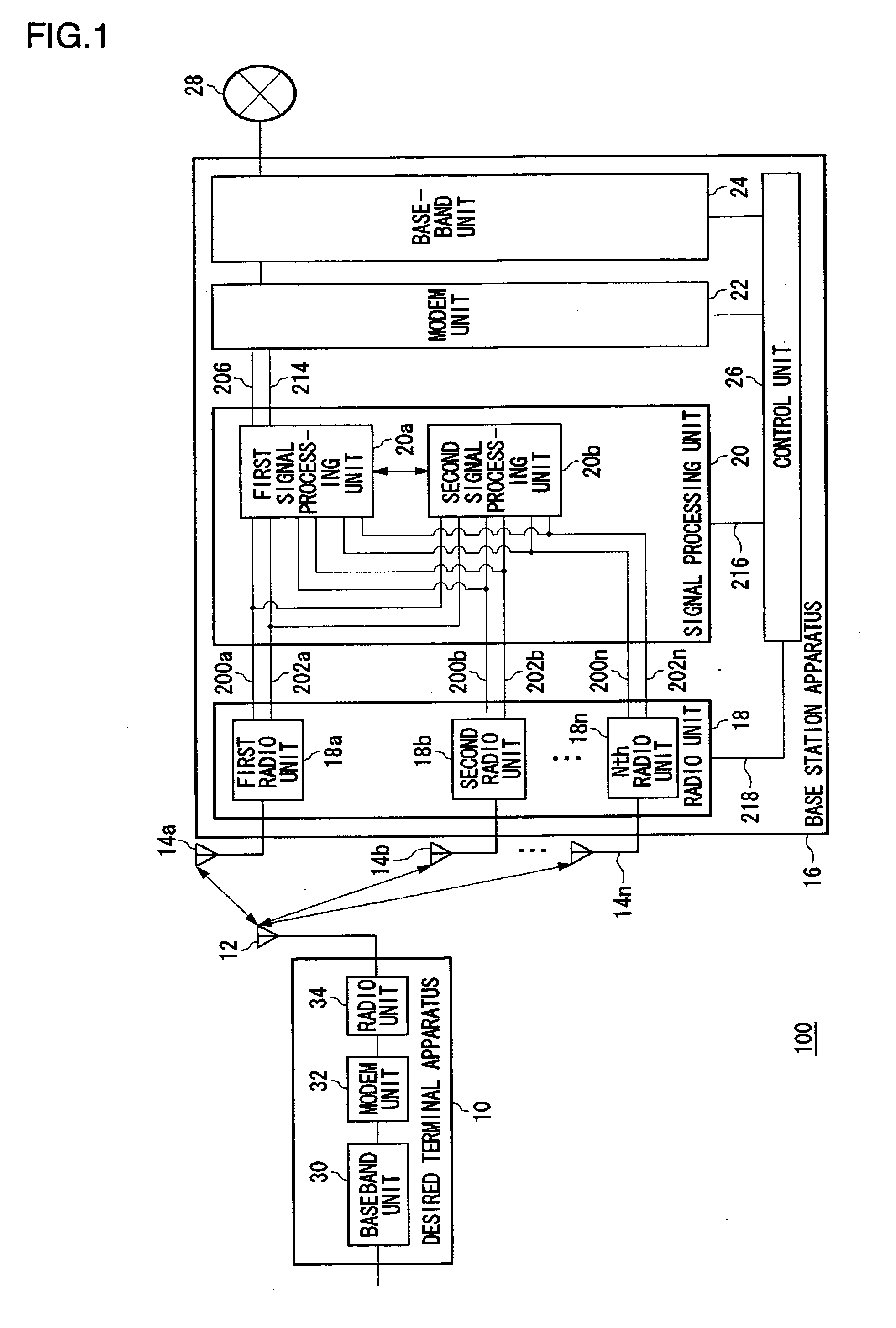
[0051] A first embodiment according to the present invention relates to a base station apparatus which can be connected to predetermined terminal apparatus. The base station apparatus according to the present embodiment is equipped with a plurality of antennas. A plurality of weighting factors (hereinafter referred to as "received weight vectors") are calculated adaptively based on signals which are sent from a terminal apparatus, which is a targeted party to the communication (hereinafter referred to as "desired terminal apparatus"), and which are received by the plurality of antennas of the base station apparatus. These signals received from the desired terminal apparatus are subject to an adaptive array signal processing at the time of receiving. Then, response factors (hereinafter referred to as "received response vectors") are computed based on the signals sent from the desired terminal apparatus and received by the respective antennas. Then, a plurality of weighting factors (h...
second embodiment
[0106] A second embodiment, similarly to the first embodiment, relates to a base station apparatus which computes transmission weight vectors that can form a directional pattern of an antenna for increasing the signal strength in the direction of a desired terminal apparatus and decreasing it in the direction of a virtual interception terminal apparatus. Hypothetically, where there is closeness between the directions of a desired terminal apparatus and a supposed interception terminal apparatus, the signal strength in the direction of the desired terminal apparatus would become small in the directional pattern of the antenna. To avoid such circumstances, the base station apparatus according to the present embodiment calculates the transmission weight vector by changing the virtual response vector to a virtual response vector whose directional information on the virtual interception terminal apparatus differs when there is a large correlation value between the received response vecto...
third embodiment
[0114] A third embodiment, similarly to the second embodiment, relates to a processing by which to calculate transmission weight vectors in cases where there is closeness between the directions in which the desired terminal apparatus and the virtual interceptor terminal apparatus exist. In this third embodiment, a virtual response vector having direction information of the virtual interceptor terminal apparatus different from that of an already acquired virtual response vector is newly selected, as in the second embodiment, and the transmission power is also controlled. That is, the base station apparatus estimates the power to be received by the desired terminal apparatus from the correlation value of the received response vector and virtual response vector, and, if the estimated power to be received is small, controls the transmission power to become larger. Furthermore, if the estimated power is large, the base station apparatus will control the transmission power to be even smal...
PUM
 Abstract
Description
Claims
Application Information
 - R&D
- Intellectual Property
- Life Sciences
- Materials
- Tech Scout
- Unparalleled Data Quality
- Higher Quality Content
- 60% Fewer Hallucinations
Browse by: Latest US Patents, China's latest patents, Technical Efficacy Thesaurus, Application Domain, Technology Topic, Popular Technical Reports.
© 2025 PatSnap. All rights reserved.Legal|Privacy policy|Modern Slavery Act Transparency Statement|Sitemap|About US| Contact US: help@patsnap.com


