Process of regenerative reforming

a technology of regenerative reforming and process, which is applied in the direction of catalytic naphtha reforming, organic chemistry, naphtha treatment, etc., can solve the problems of low selectivity of hydrocarbons into coke, and the contents of coke accumulated on the catalyst can be very significant, so as to achieve the same level of rigor of operating conditions, less catalyst, and economic attractive

Active Publication Date: 2004-09-16
INST FR DU PETROLE
View PDF10 Cites 11 Cited by
  • Summary
  • Abstract
  • Description
  • Claims
  • Application Information

AI Technical Summary

Benefits of technology

[0017] The distribution zone will distribute the catalyst flow that is obtained from the regeneration zone into a certain number of parallel flows that supply at least two reactors, optionally each of the reactors of the series. The circulation of the catalyst inside each reactor is always carried out in a moving bed, as well as inside the regeneration zone. The zone for mixing the catalyst that is recovered at the outlet of each reactor, as well as the distribution zone of the regenerated catalyst are an integral part of the invention. The feedstock is introduced into the first reactor of the series and the intermediate effluents circulate in succession from one reactor to another. Each intermediate effluent that leaves a reactor of the series is heated by a reheating furnace that makes it possible to bring the temperature of said effluent at the inlet of the next reactor in the series to the desired level.
[0048] The invention therefore relates to a process for treatment of fractions of hydrocarbons, of regenerative reforming type, using a series of at least two reactors, forming the reaction zone, whereby the feedstock and the intermediate effluents pass through the reactors in succession and each reactor operates in a moving bed, and whereby said process has a regeneration zone that makes it possible to eliminate the coke that is deposited on the catalyst during reactions, and whereby said process is characterized in that the regenerated catalyst that is obtained from said regeneration zone directly supplies at least two reactors of the series from a common distribution zone, is collected at the outlet of the reaction zone in a mixing zone where it is homogenized and, at the outlet of this mixing zone, is brought into the regeneration zone.

Problems solved by technology

Although the transformation selectivity of the hydrocarbons into coke is very low, the contents of coke accumulated on the catalyst can be very significant.
A loss in catalytic activity, penalizing the operation of each reactor and causing the following reactors to be operated at a higher temperature than the one that could be used if there were no coke deposition on the catalyst that enters the reactors, results therefrom.

Method used


Image

  • Process of regenerative reforming
  • Process of regenerative reforming
  • Process of regenerative reforming

Examples


example 2

According to the Invention

[0063] So as to carry out comparisons on an identical basis, the research octane number of the reformate is kept at 102 in all of the following examples.

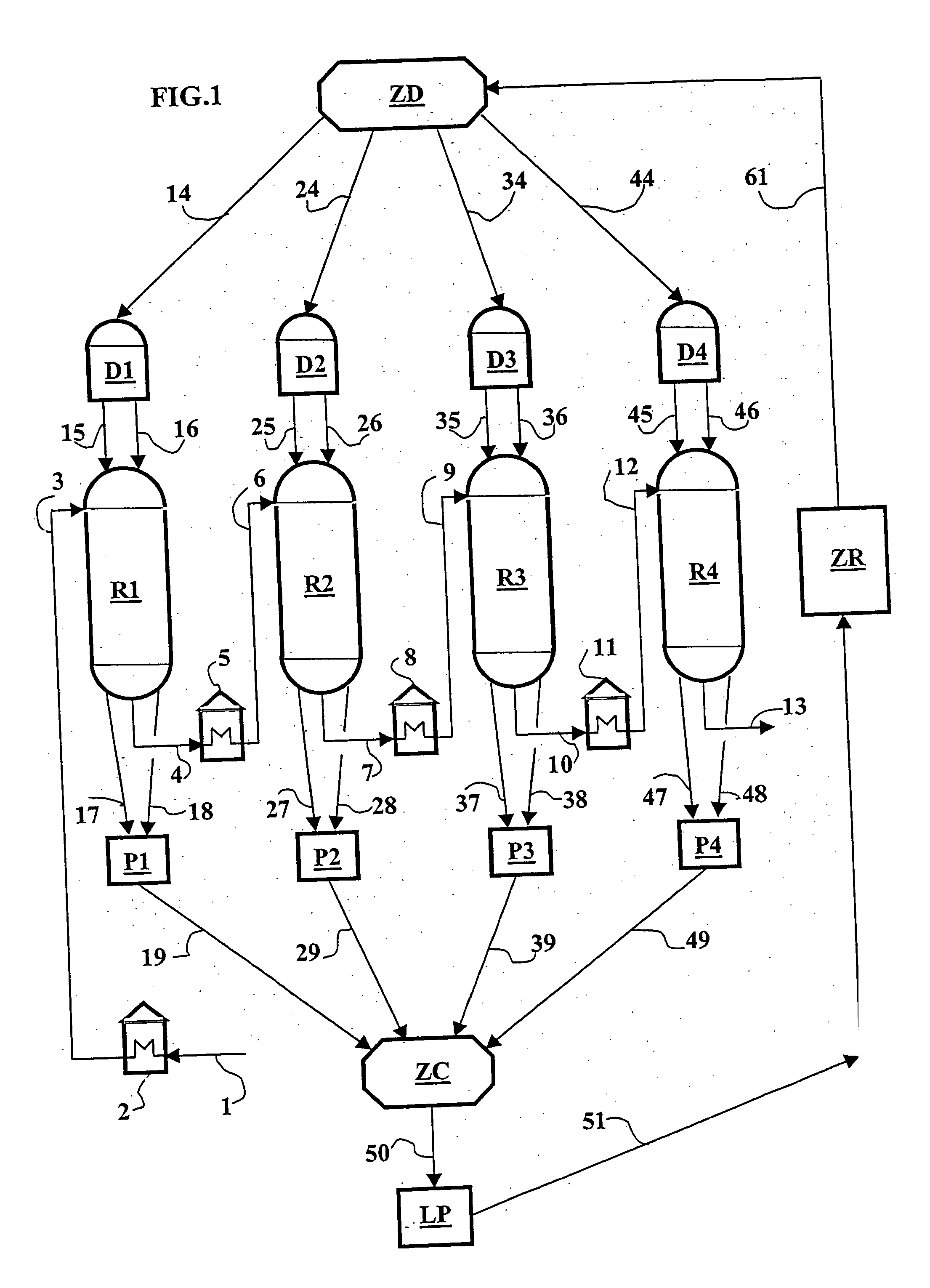
[0064] In this example, the catalyst that is obtained from the regeneration zone supplies each of the four reactors in parallel.

[0065] The operating pressure in the separator tank is kept at 0.23 MPA, and the other operating parameters are indicated in Table 1.

[0066] A reduction of the coke content of the catalyst at the outlet of each reactor is noted relative to the first example. In particular, at the outlet of the last reactor, the coke drops to 3.76% from 5.87% at the outset. Furthermore, the reformate yield is higher.

example 3

According to the Invention

[0067] In this example, the operating pressure in the separator tank is lowered to 0.08 MPa. The H2 / HC ratio is kept at 2, and the volumetric flow rate is increased to 2.5 h.sup.-1, or an increase in the feedstock flow rate of 25%, or expressed equivalently, a reduction in the amount of catalyst of 20%. The reformate yield passes to 90.55% (at the outset at 88.9%). It is also noted that the coke yield is raised to 5.02% from 3.76% in Example 2, but it remains less than that at the outset (5.87%).

example 4

According to the Invention

[0068] In this example, the operating pressure is kept at 0.08 MPa, but the H2 / HC ratio is lowered to 1.3 so as to compare the fourth example with the starting conditions (Example 1) with the same level of coke. The reformate yield that passes to 91.44% (or 2.5 points more relative to the starting conditions) is again improved, and the coke yield virtually rejoins the value at the outset or 5.8%.

[0069] On the basis of a 100 T / h capacity, the gain in productivity on the reformate with a constant quality corresponds in this fourth example to a production difference of about 20,000 T / year of reformate, or a cash flow of more than about 1.2 million euros per year (baseline: 6 centimes / kg).

[0070] This new concept therefore makes it possible to obtain a better selectivity of operation with the same level of rigor of operating conditions (temperature and octane number) and this with a smaller amount of catalyst.


PUM

PropertyMeasurementUnit
operating pressureaaaaaaaaaa
molar ratioaaaaaaaaaa
boiling pointaaaaaaaaaa

Abstract

In this invention, a new structure for the units using a series of moving beds, characterized by a direct supply of regenerated catalyst from at least two of the reactors of the series, is described. The feedstock and the intermediate effluents continue to circulate in succession relative to the reactors. The invention makes it possible in particular to cross a new threshold in the reduction of the operating pressure of the units.

Description

TECHNOLOGICAL BACKGROUND[0001] The invention relates to the moving-bed processes such as gasoline reforming (reforming according to English terminology) for the improvement of the octane number of petroleum fractions that are located in the range of gasolines, i.e., at the starting point between 70.degree. C. and 110.degree. C., and at the end boiling point between 150.degree. C. and 180.degree. C. More generally, the invention relates to any process that uses a series of moving-bed reactors such as are found in the spraying process (aromatizing according to English terminology) or the process for dehydrogenating normal paraffins. The following description refers to the reforming process with continuous regeneration that will be designated by the name of regenerative reforming. The process for reforming gasolines started in the 1950s and has since known important technological developments that are often linked to the appearance of new generations of catalysts according to three suc...

Claims


Application Information

Patent Timeline
Patent Type & Authority Applications(United States)
IPC IPC(8): B01J8/08C10G35/12C10G59/02
CPCB01J8/08B01J2219/00006C10G59/02C10G35/12B01J2219/0004
Inventor SANCHEZ, ERICCASANAVE, DOMINIQUE
Owner INST FR DU PETROLE
Why Eureka
Try Eureka