Dosing system for use in an exhaust system of a combustion engine

a technology of combustion engine and exhaust system, which is applied in the direction of machine/engine, water supply installation, electric control of exhaust treatment, etc., can solve the problems of poor atomization, poor control of the amount of deposited, and the formation of crystals or amorphous structures

Inactive Publication Date: 2011-12-29
GRUNDFOS NONOX AS
View PDF8 Cites 9 Cited by
  • Summary
  • Abstract
  • Description
  • Claims
  • Application Information

AI Technical Summary

Benefits of technology

[0019]The first fluid may flow out of the nozzle outlet intermittently at least when the request value is below the threshold value. By intermittently is preferably meant that the valve is open for a period of time followed by a period in which it is closed. The opening time and closed time may be of equal or different length. The intermittent flow enables that even small doses of the first fluid can flow through the nozzle under high pressure without unnecessary use of first fluid. A high pressure is used to flush the nozzle and thereby remove possible deposits formed in the nozzle.
[0020]In some embodiments of the invention, the nozzle comprises the valve. Hereby a compact and fluid-tight solution may be obtained. Alternatively the nozzle and valve are separate units which are to be connected by any suitable means preferably while ensuring a non-leaking connection.

Problems solved by technology

The introduction of reducing agents often results in deposits in the form of crystals or amorphous structures building up in the nozzles used to deliver the reducing agent.
These deposits grow in size over time and thereby result in a poorer atomization, a poorer control of the delivered amount and eventually a total clogging up of the nozzle outlet.

Method used


Image

  • Dosing system for use in an exhaust system of a combustion engine
  • Dosing system for use in an exhaust system of a combustion engine
  • Dosing system for use in an exhaust system of a combustion engine

Examples


Embodiment Construction

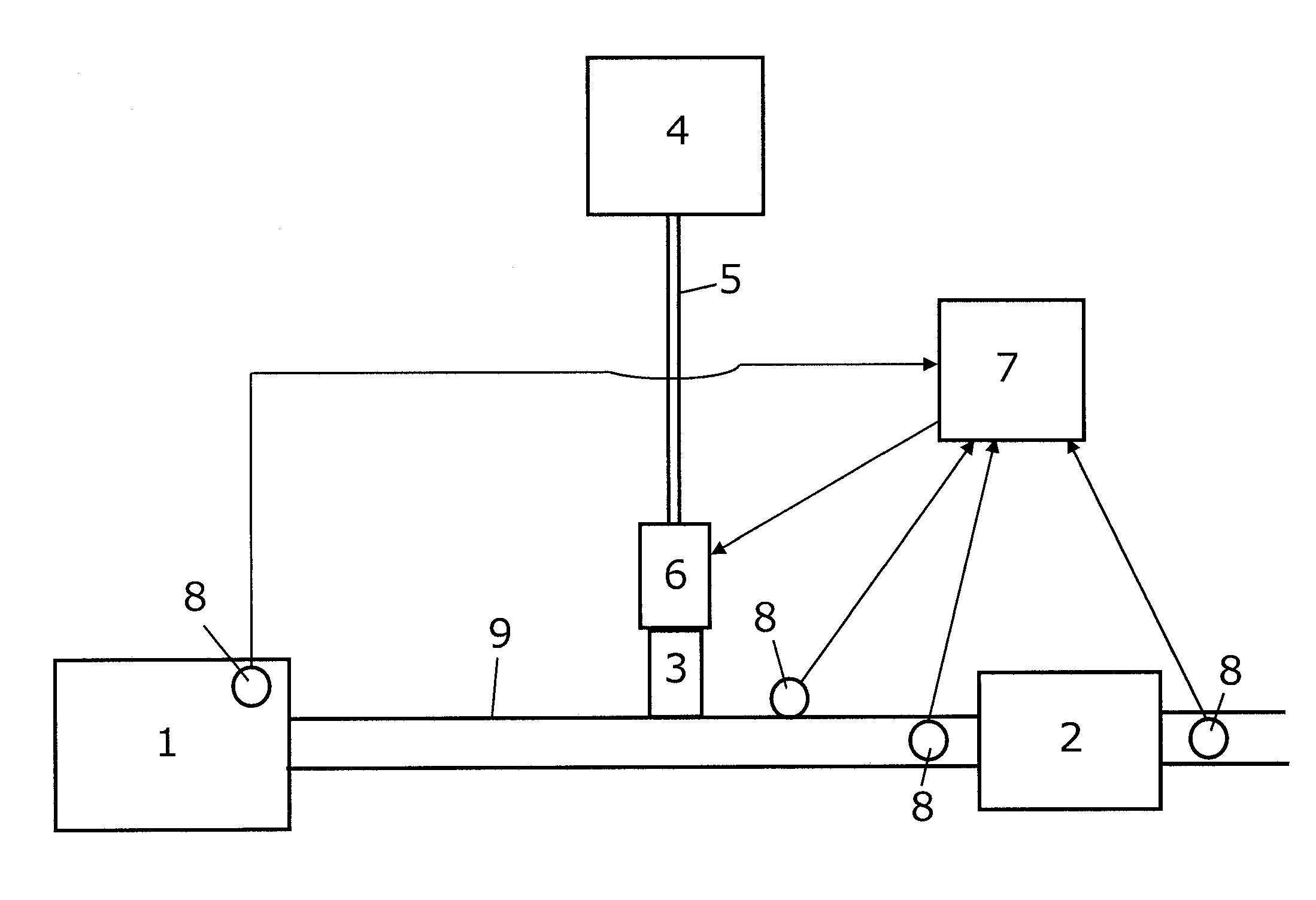
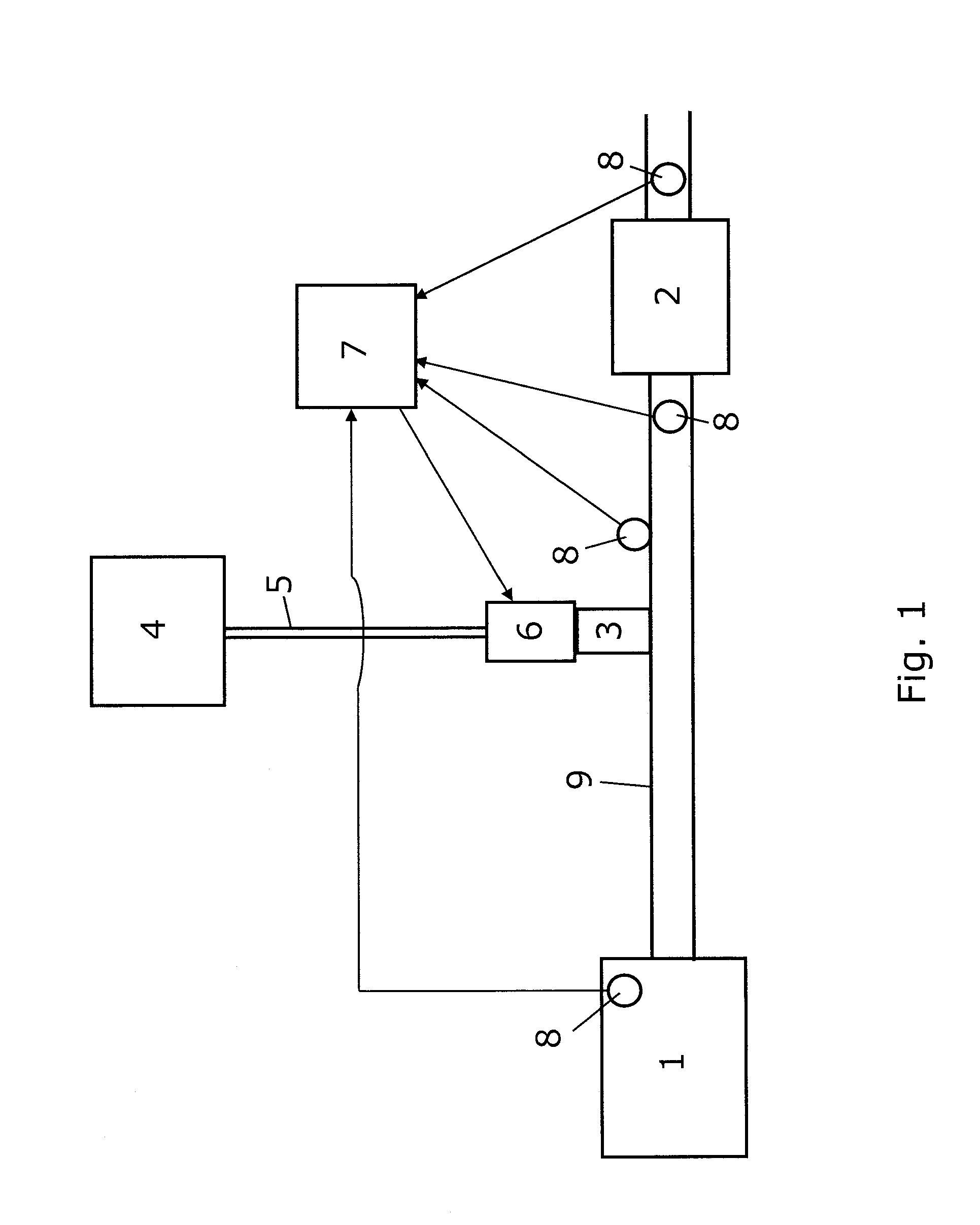
[0041]The following description of a preferred embodiment of the invention relates to a combustion system having a dosing system according to the present invention. A schematic illustration of such a combustion system is given in FIG. 1. In this embodiment the first fluid referred to above is a reducing agent, and the second fluid is exhaust gas from a combustion engine.

[0042]In a combustion engine vehicle, the exhaust gas leaving the engine 1 comprises nitrogen oxides before it enters into the catalytic system 2. After the exhaust gas has passed through the catalytic system 2, the gas comprises nitrogen and water which is typically discharged to the environment. It is known that this process is significantly improved if a reducing agent, such as liquefied urea, is sprayed into the exhaust gas by use of a nozzle 3 before it enters the catalytic system 2. The reduction agent is stored in a tank 4 and led to the nozzle 3 via a pipe 5 and a valve 6. The tank 4 in which the reducing age...


PUM


Abstract

The present invention relates to a dosing system for dosing a first fluid, preferably flowing in a first flow passage (5) into a stream of a second fluid, preferably flowing in a second flow passage (9). The system may e.g. be used to dose a reducing agent into an exhaust gas from a combustion engine (1). The system comprises a valve (6), a nozzle (3) having an outlet arranged downstream of the valve (6), a flow passage (5) through which the first fluid can flow from a reservoir (4) to the nozzle outlet via the valve (6), and a control system (7) adapted to receive input from one or more sensors (8) and based thereon determine a request value based on which a valve opening period is determined. The valve opening period is different from zero and independent on the request value when the request value is below a predefined threshold value. The invention further relates to an exhaust system comprising such a dosing system and to a method of dosing a first fluid into a stream of a second fluid by use of such a dosing system.

Description

FIELD OF THE INVENTION[0001]The present invention relates to a dosing system for dosing a first fluid into a stream of a second fluid, and in particular to a dosing system for dosing a reducing agent into an exhaust pipe of a combustion engine.BACKGROUND OF THE INVENTION[0002]In order to lower the emission of pollutants, such as nitrogen oxides, from the exhaust gasses of combustion engines, reducing agent, such as e.g. liquefied urea, is often introduced into the exhaust systems. This is typically done by use of a nozzle that ensures atomization of the reducing agent. In some dosing systems, the current amount of reducing agent is determined to correlate to the current demand which depends on e.g. the fuel consumption. The introduction of reducing agents often results in deposits in the form of crystals or amorphous structures building up in the nozzles used to deliver the reducing agent. These deposits grow in size over time and thereby result in a poorer atomization, a poorer con...

Claims


Application Information

Patent Timeline
Patent Type & Authority Applications(United States)
IPC IPC(8): F01N3/00F17D3/00F16K11/00
CPCF01N3/208F01N9/00F01N11/002F01N2260/02F01N2260/024F01N2610/02Y02T10/24F01N2610/146F01N2900/0411F01N2900/08F01N2900/1811Y02T10/47F01N2610/11Y02T10/12Y02T10/40Y10T137/0324Y10T137/87676Y02A50/20
Inventor PLOUGMANN, JAN
Owner GRUNDFOS NONOX AS
Why Eureka
Try Eureka