Method of determining the imaging equation for self calibration with regard to performing stereo-PIV methods

a self-calibration and imaging equation technology, applied in the direction of full-field flow measurement, indication/recording movement, television systems, etc., can solve the problems of high cost of calibration, easy errors, and high percentage of errors at strong velocity gradients

Inactive Publication Date: 2004-09-23
LAVISION
View PDF14 Cites 14 Cited by
  • Summary
  • Abstract
  • Description
  • Claims
  • Application Information

AI Technical Summary

Problems solved by technology

This is very difficult to achieve; the smallest deviations from 0.6.degree. already result in a position inaccuracy of 10 pixels on the image border when determining the vector in the two image sectors, with said deviations possibly resulting in a high percentage of errors at strong velocity gradients.
Calibration is performed at high expense.
Or the angle or the spacing has to be determined, which is also complicated and prone to errors.
It is e.g., difficult, when determining the spacing, to determine the distance between the zero point on the calibration plate and an imaginary camera pinhole position.
With many objects, such as microchannels for example, so-called in situ calibration cannot be realized, or is only to be performed at high expense, since it is very difficult to accommodate the calibration plate therein.
However, this method cannot be readily applied to the stereo-PIV technique partly because determining the point correspondences between the cameras is difficult.
The disadvantage of this method is that the cameras have to be moved very fast.
There is always a risk of the point correspondences having been erroneously determined.
As a result, the cross-correlation between the two camera images is very prone to errors since the right correlation peak is strongly blurred and is often lower than a random noise peak so that it is not recognized as such.

Method used


Image

  • Method of determining the imaging equation for self calibration with regard to performing stereo-PIV methods
  • Method of determining the imaging equation for self calibration with regard to performing stereo-PIV methods
  • Method of determining the imaging equation for self calibration with regard to performing stereo-PIV methods

Examples


example 2

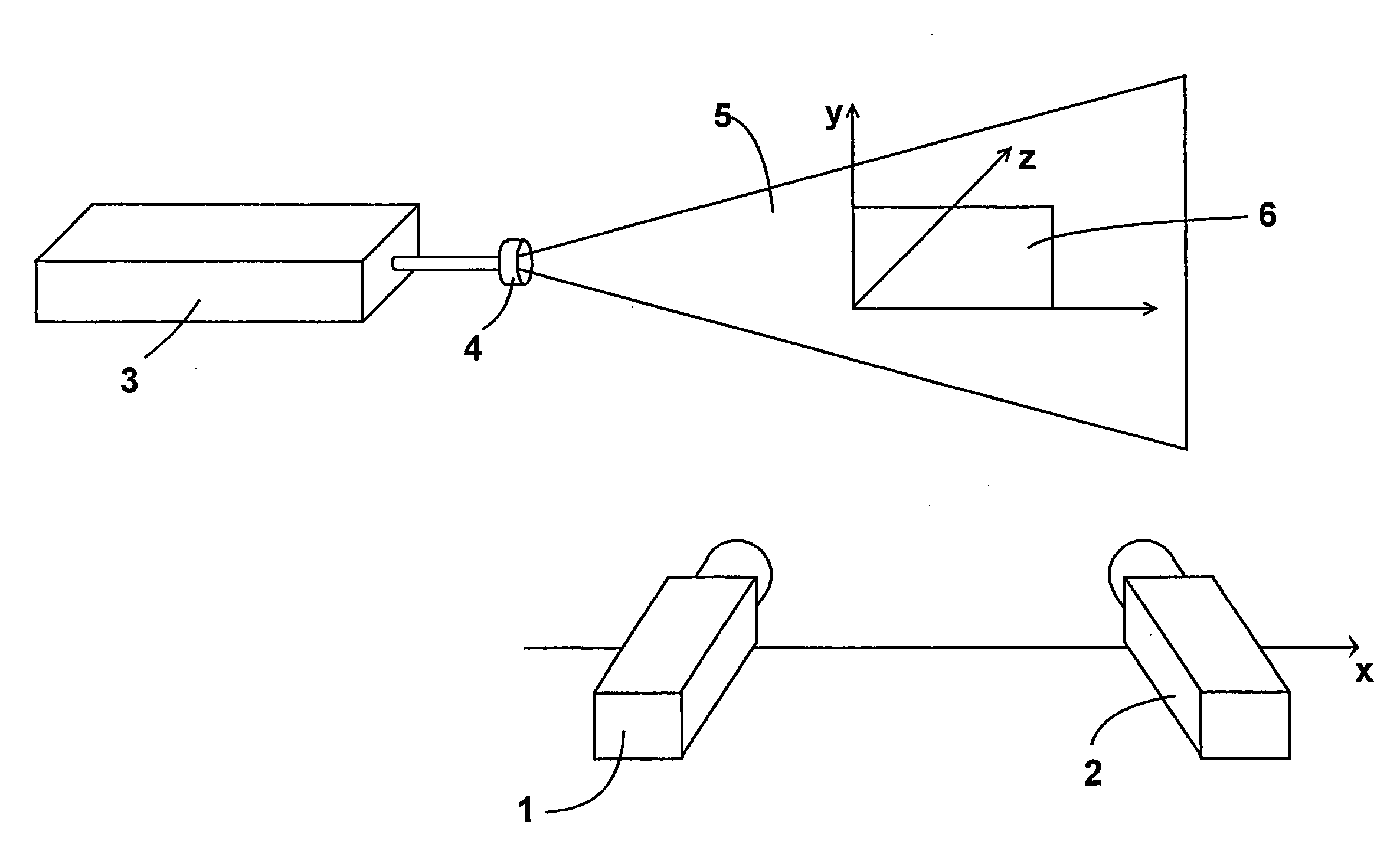
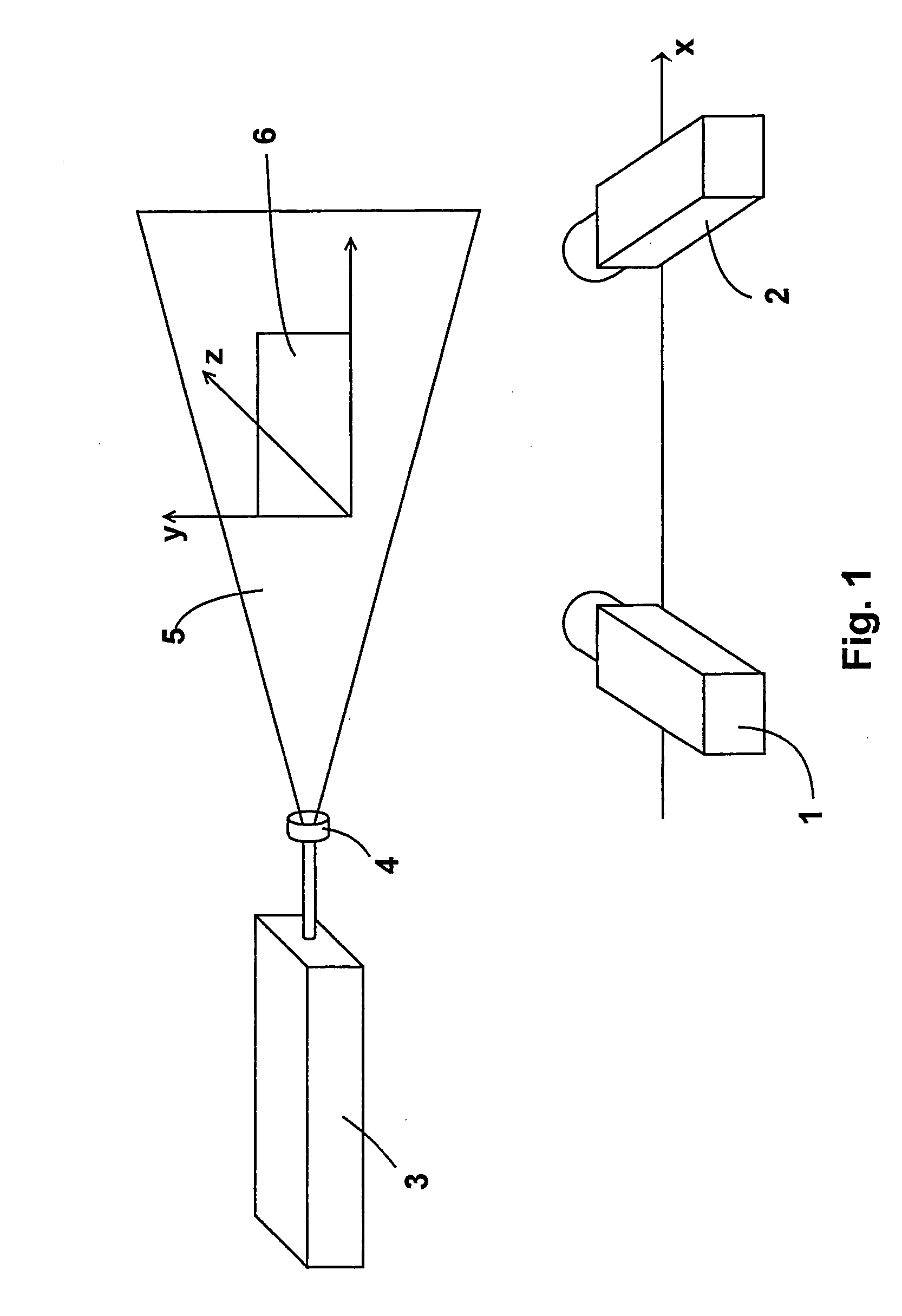
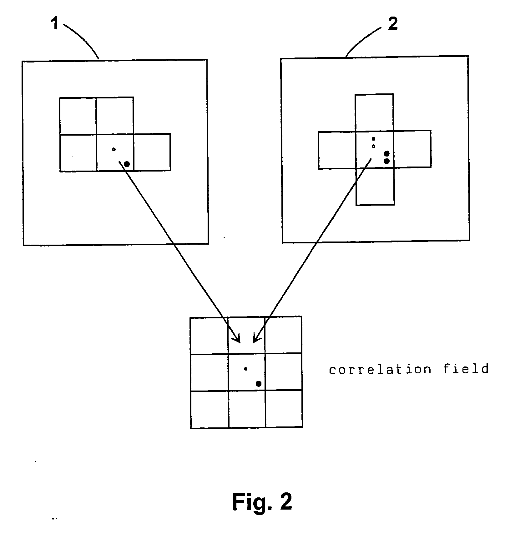
[0025] The same experimental set-up is used as in Example 1. It is also assumed that the objective of the camera is angled relative to the camera plane in order to fulfill the Scheimflug condition so that all of the particles in the illuminated section are in focus. In this example, no previous calibration is provided, an imaging equation is intended to be determined from the very point correspondences. This is achieved using a direct approximation method in which the missing image parameters are fitted. Since there are too many free parameters, certain assumptions must be made in order to converge on a solution. There are various possibilities to reduce the number of free parameters with the help of known conditions:

[0026] It is assumed that it is known from a previous calibration of the Scheimflug adapter, which has only to be carried out once, how the principal point is displaced as a function of the angle, or the Scheimflug condition is calculated directly from the geometry. Acc...


PUM


Abstract

The subject matter of the invention is a method for determining the imaging equation for self calibration with regard to performing stereo-PIV methods on visualized flows, said method being comprised of at least two cameras and one image sector, with the cameras viewing approximately the same area of the illuminated section but from different directions, the point correspondences between the two cameras being determined by measuring the displacement of the respective interrogation areas in the camera images using optical cross-correlation, the imaging equation being determined by means of approximation methods, using known internal and external camera parameters.

Description

1. FIELD OF THE INVENTION[0001] The invention relates to a method of determining the imaging equation for self calibration with regard to performing stereo-PIV methods.[0002] For a fuller understanding of the invention, the term "PIV method" will first be explained. PIV stands for Particle Image Velocimetry. PIV serves to image the flow conditions of a gas or a fluid in a space (e.g., DE 199 28 698 A1). To carry out such a PIV method, a laser or another suited light source is needed, said light source producing in the flow of a medium such as a gas or a fluid what is called an illuminated section, said illuminated section being viewed by at least one camera. With one camera only being oriented normal to the illuminated section, the two velocity components may be determined in the illumination plane whereas, with at least two cameras (stereo-PIV) viewing the illuminated section from different angles, all of the three components are determined. As already explained, the PIV technique ...

Claims


Application Information

Patent Timeline
Patent Type & Authority Applications(United States)
IPC IPC(8): H04N17/00G01B11/00G01P5/00G01P5/20G01P5/22G01P13/00
CPCG01P5/001G01P5/22G01P5/20A23V2002/00A23V2200/218A23L11/07
Inventor WIENEKE, BERNHARD
Owner LAVISION
Why Eureka
Try Eureka