Optical inspection system, illumination apparatus and method for use in imaging specular objects based on illumination gradients

an optical inspection system and illumination apparatus technology, applied in the field of optical inspection systems, can solve the problems of prone to errors, labor-intensive manual inspection process of these images, and conventional optical inspection systems that do not have the capability to produce images in more than two dimensions, and severely quantized surface slope information

Inactive Publication Date: 2004-09-23
AGILENT TECH INC
View PDF46 Cites 85 Cited by
  • Summary
  • Abstract
  • Description
  • Claims
  • Application Information

AI Technical Summary

Problems solved by technology

The manual inspection process of these images is labor-intensive and prone to errors.
However, conventional optical inspection systems do not have the capability to produce images in greater than two dimensions.
In most optical inspection systems...

Method used


Image

  • Optical inspection system, illumination apparatus and method for use in imaging specular objects based on illumination gradients
  • Optical inspection system, illumination apparatus and method for use in imaging specular objects based on illumination gradients
  • Optical inspection system, illumination apparatus and method for use in imaging specular objects based on illumination gradients

Examples


Embodiment Construction

[0039] The numerous innovative teachings of the present application will be described with particular reference to the exemplary embodiments. However, it should be understood that these embodiments provide only a few examples of the many advantageous uses of the innovative teachings herein. In general, statements made in the specification do not necessarily delimit any of the various claimed inventions. Moreover, some statements may apply to some inventive features, but not to others.

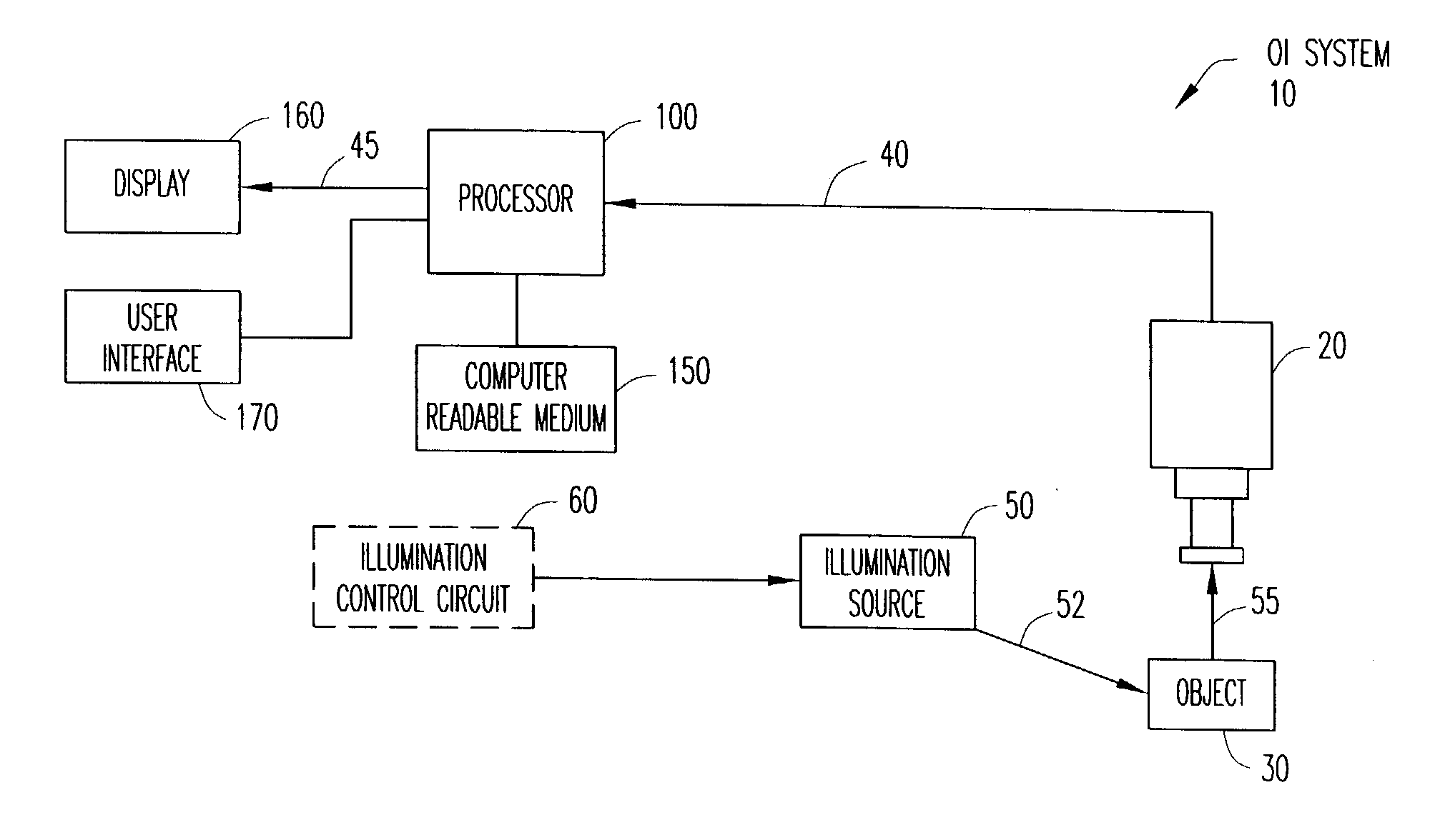
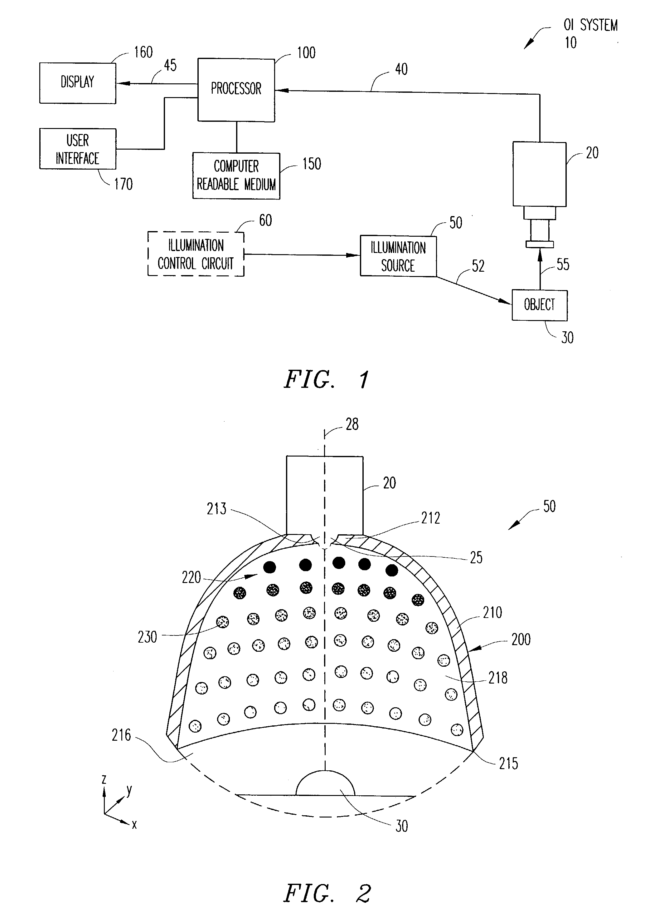
[0040] Referring now to FIG. 1, there is illustrated a simplified schematic of an optical inspection (OI) system 10 capable of rendering a three-dimensional image 45 of the surface of an object 30, which can have both specular and diffuse surface reflection elements, in accordance with embodiments of the present invention. The OI system 10 includes an illumination source 50 for illuminating the surface of an object 30 and a sensing apparatus (e.g., camera) 20 for capturing an image of the surface of the...


PUM


Abstract

An optical inspection system uses an illumination gradient to gradually spatially vary the intensity and/or specular characteristics of the illumination reflected from the surface of a specular object to determine surface gradients of the object. The surface gradients can be used to reconstruct a three-dimensional image of the object. The illumination gradient can be produced by an illumination apparatus that includes circular arrays of light-emitting elements. The illumination gradient can also be produced using an optical element that gradually alters the illumination intensity of the reflected illumination in accordance with the incidence characteristics of the reflected illumination on the optical element. The illumination gradient enables the use of numerous illumination angles to reduce error in estimated surface gradients without increasing imaging or processing time.

Description

[0001] This U.S. Nonprovisional Application for Patent is related by subject matter to copending and commonly assigned Nonprovisional U.S. patent application Ser. No. ______ (Attorney Docket No. 10030330), Ser. No. ______ (Attorney Docket No. 10030418) and Ser. No. ______ (Attorney Docket No. 10030331). Nonprovisional U.S. patent application Ser. No. ______ (Attorney Docket No. 10030330), Ser. No. ______ (Attorney Docket No. 10030418) and Ser. No. ______ (Attorney Docket No. 10030331) are hereby incorporated by reference in their entirety.[0002] 1. Technical Field of the Invention[0003] The present invention relates generally to the field of optical inspection systems. More particularly, the present invention relates to optical inspection systems for imaging specular objects using illumination gradients.[0004] 2. Description of Related Art[0005] Optical inspection systems are used in the machine vision industry to inspect objects, such as solder joints and components, on printed cir...

Claims


Application Information

Patent Timeline
IPC IPC(8): G01B11/25G01N21/88G01N21/956
CPCG01B11/2509G06T7/0057G01N21/95684G01N21/8806G06T7/521
Inventor BAER, RICHARD L.ZHANG, XUEMEIVOOK, DIETRICH W.
Owner AGILENT TECH INC
Why Eureka
Try Eureka