

Handle arrangement for a power tool
a power tool and handle technology, applied in the field of power tools, can solve the problems of operator's inability to effectively operate the saw, relative confinement of the saw operation area, etc., and achieve the effect of better control of the saw
- Summary
- Abstract
- Description
- Claims
- Application Information
AI Technical Summary
Benefits of technology
Problems solved by technology
Method used
Image

Examples
Embodiment Construction
Cross Reference To Related Applications
[0001] The present application is a continuation-in-part of co-pending Application Serial No. 10 / 011,251, filed December 3, 2001.
Background of Invention
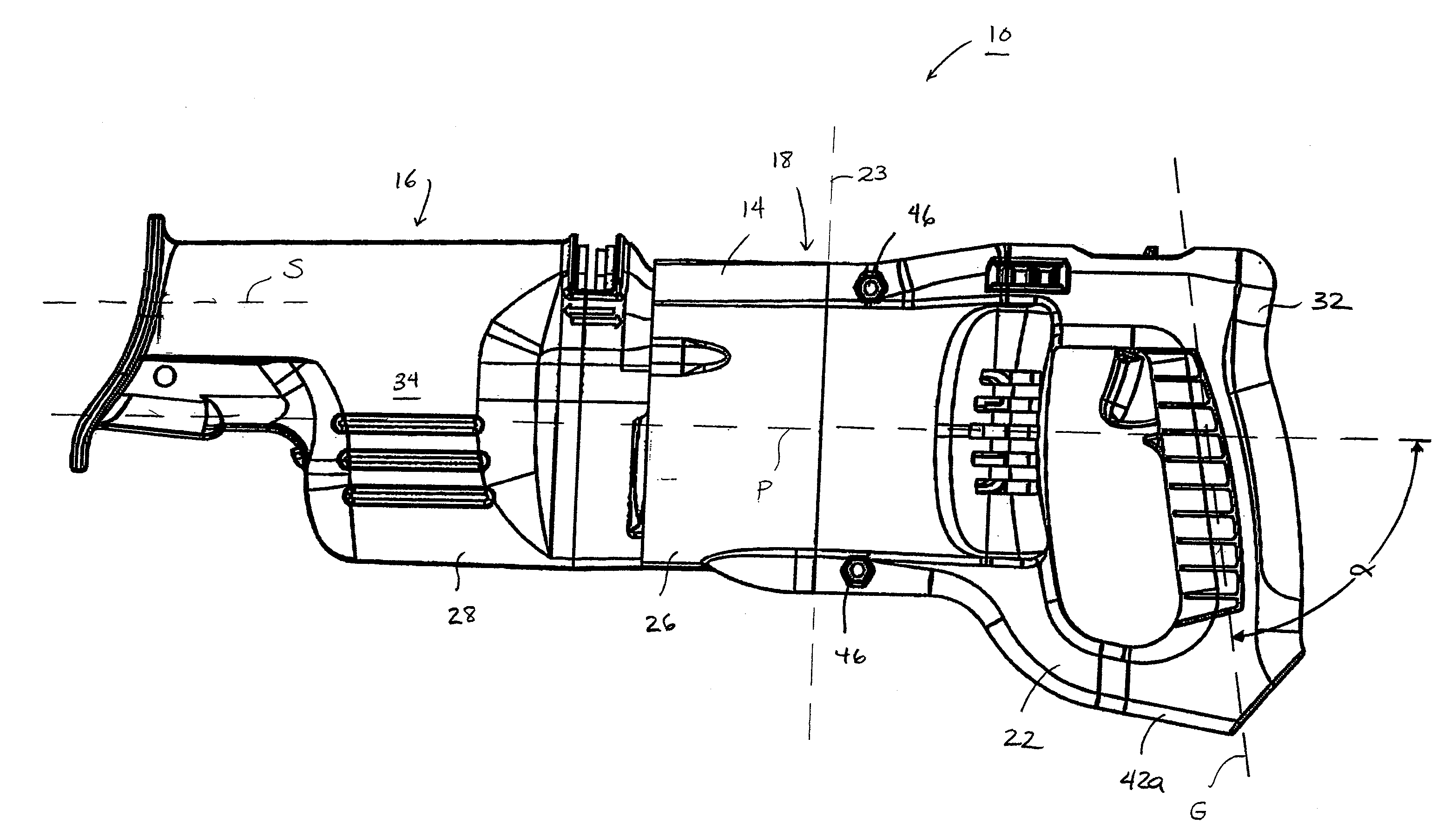
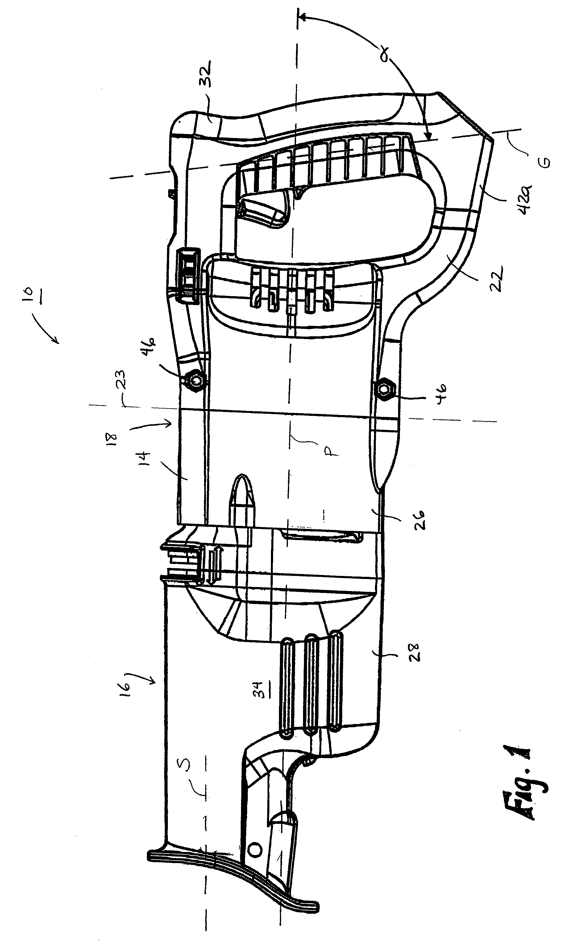
[0002] The present invention relates to power tools and, more particularly, to a handle arrangement for a power tool, such as a reciprocating saw.
[0003] A power tool, such as a reciprocating saw, generally includes a housing supporting a motor and a drive mechanism. The motor and the drive mechanism operate to drive a spindle and a tool element supported by the spindle. In a typical reciprocating saw, a main operator's handle is integrally formed with the rearward portion of the housing. Generally, the fixed-handle reciprocating saw is gripped by the operator with one hand on the main operator's handle and a second hand on a forward portion of the housing.
Summary of Invention
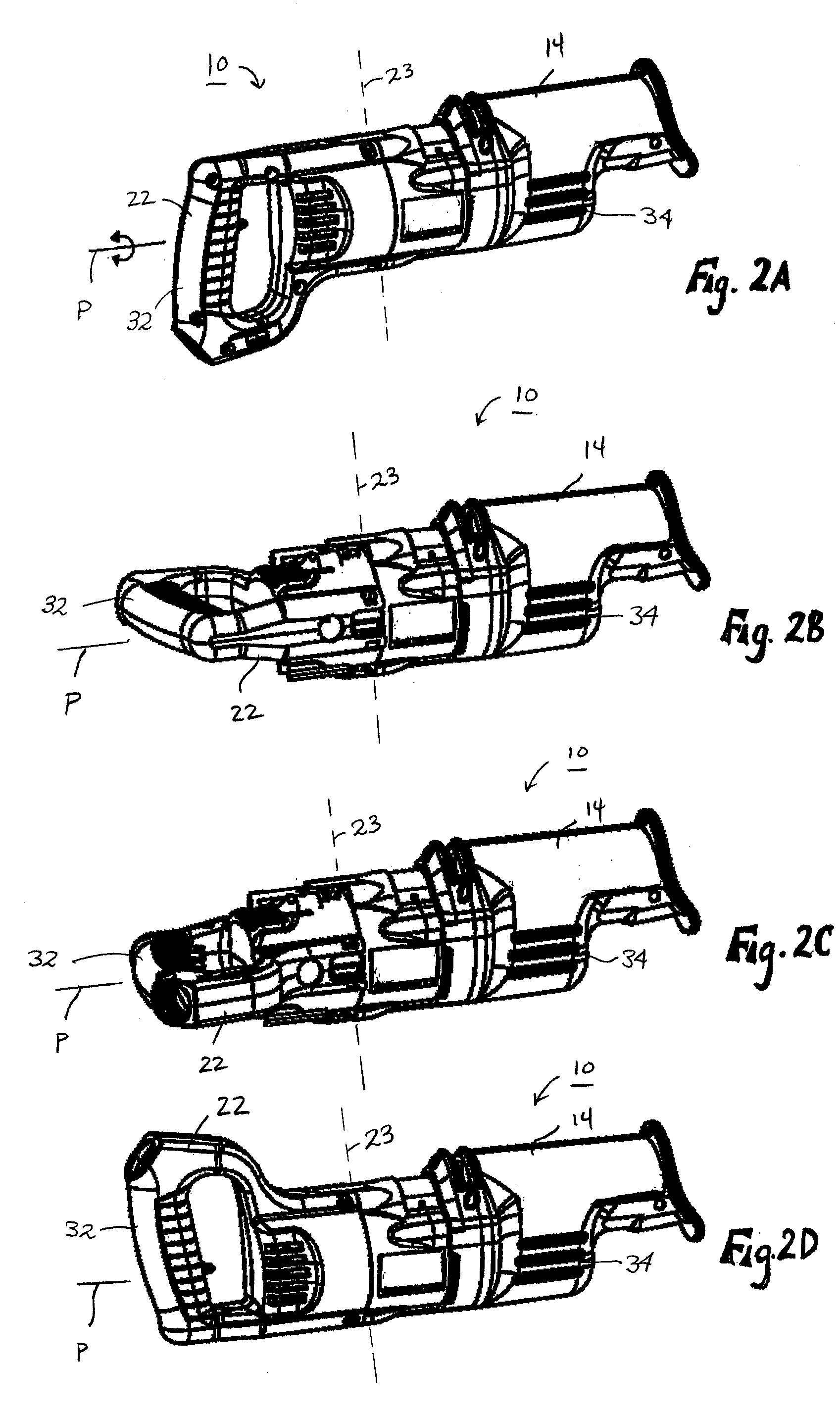
[0004] In some cutting operations, the operator may prefer a different handle position than the position in which the hand...
PUM
| Property | Measurement | Unit |
|---|---|---|
| non-perpendicular angle | aaaaa | aaaaa |
| non-perpendicular angle | aaaaa | aaaaa |
| angle | aaaaa | aaaaa |
Abstract
Description
Claims
Application Information