Instantaneous compact fluid heater

a fluid heater and instantaneous technology, applied in water heaters, ohmic resistance heating, immersion heating arrangements, etc., can solve the problems of high cost, complicated design, loss of valuable energy, etc., and achieve the effect of reducing energy loss, simple construction, and occupying less spa

Inactive Publication Date: 2004-10-07
DDA ENERGIE
View PDF5 Cites 4 Cited by
  • Summary
  • Abstract
  • Description
  • Claims
  • Application Information

AI Technical Summary

Benefits of technology

[0025] An advantage of the present invention is that the water heater is compact and takes up less space as compared to, prior water heaters.
[0026] Another advantage of the present invention is that the water heater may selectively heat water upon demand.
[0027] A further advantage of the present invention is that it minimizes loss of energy out of the reservoir.
[0028] A further advantage of the present invention is that the water heater while meeting conventional norms is of simple construction, relatively easy to use and economical.
[0029] Other objects, advantages and features of the present invention will become more apparent upon reading of the following non restrictive description of preferred embodiments thereof, given by way of example only with reference to the accompanying drawings.
[0030] In the appended drawings like reference numerals denote like elements throughout and in which:

Problems solved by technology

A drawback with the conventional water heater is that there is a loss of valuable energy by heat convection out of the tank or reservoir.
A drawback with the prior art is inefficiency, high cost and complicated design.

Method used


Image

  • Instantaneous compact fluid heater
  • Instantaneous compact fluid heater
  • Instantaneous compact fluid heater

Examples


Embodiment Construction

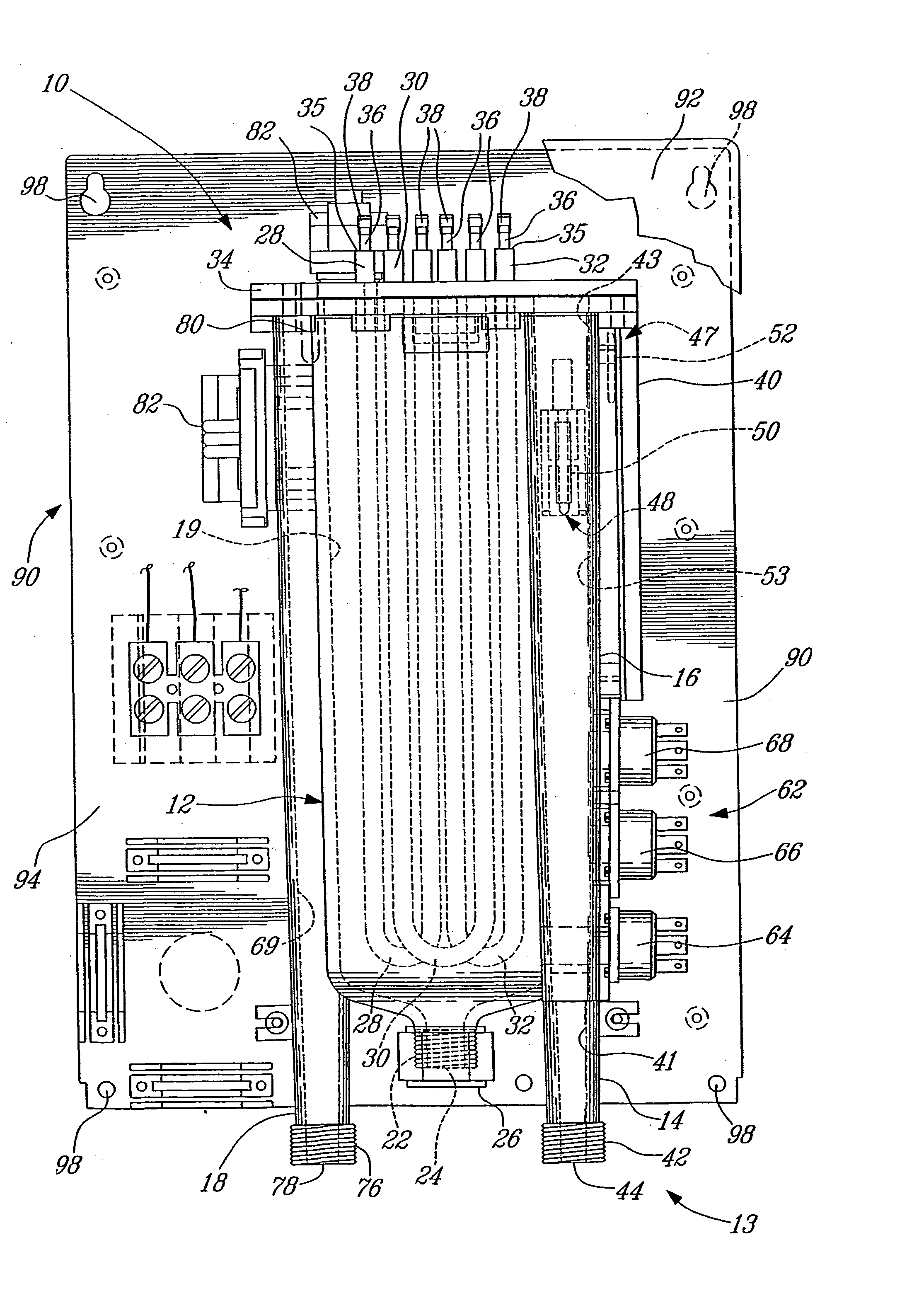
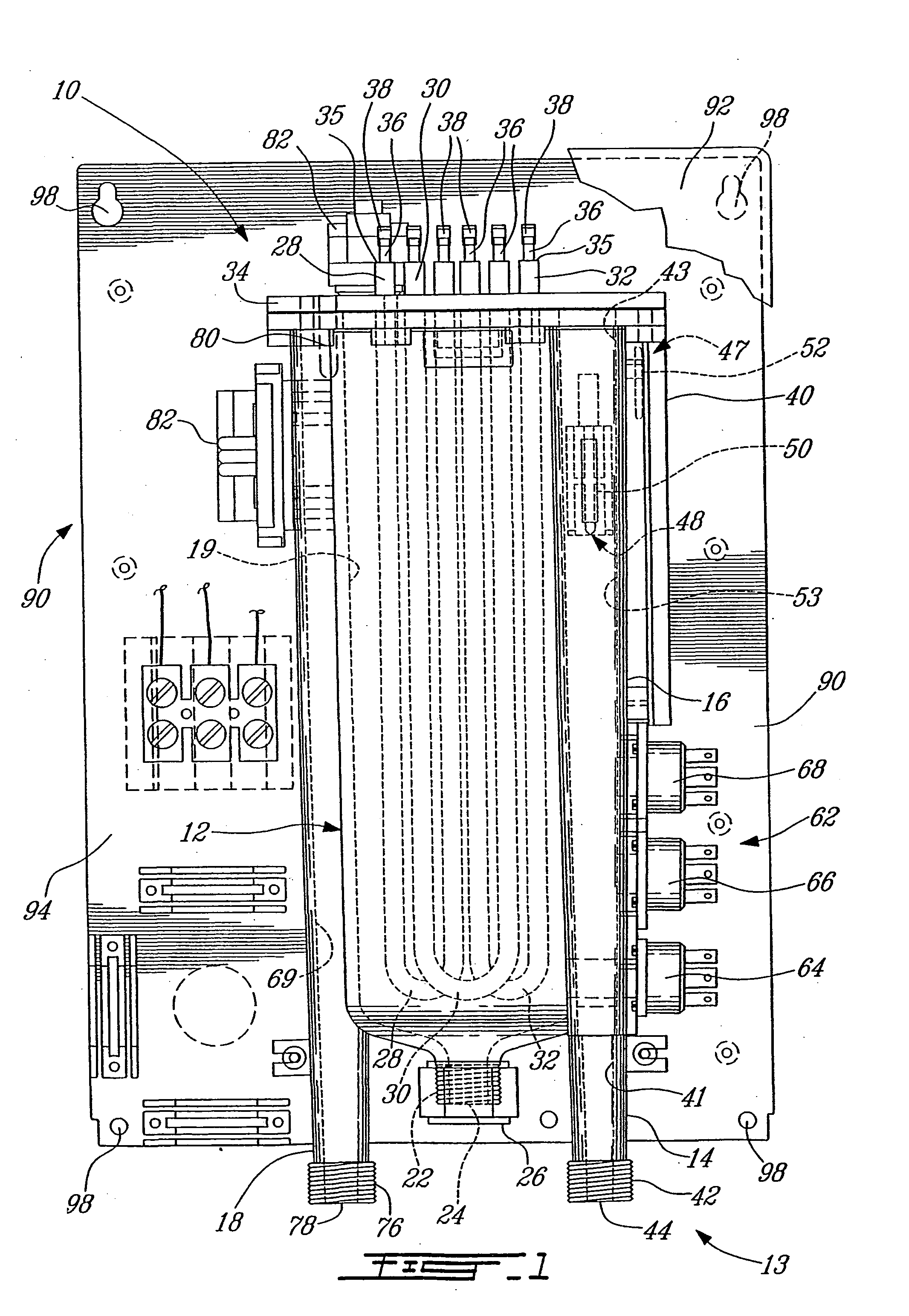
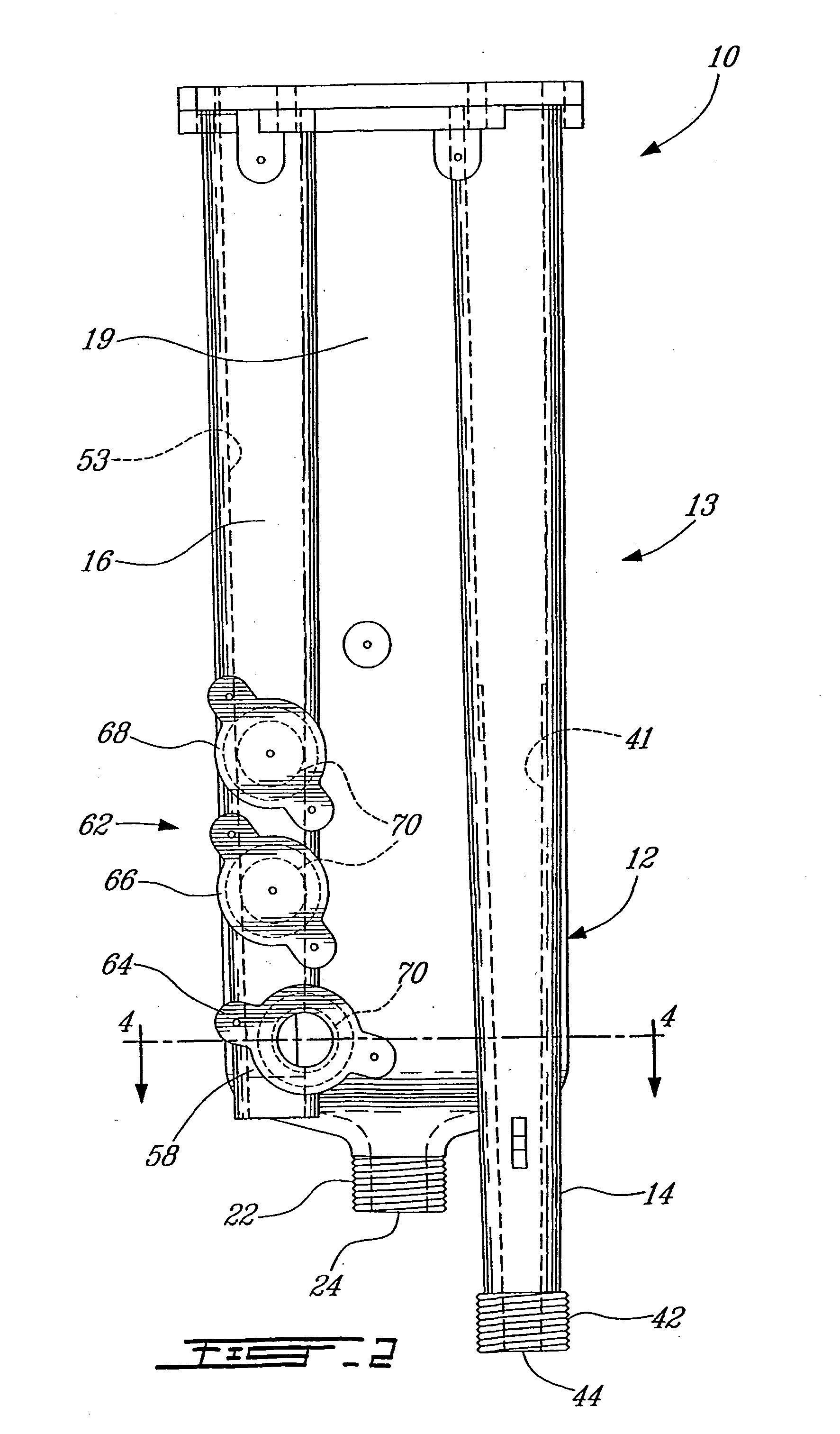
[0039] With reference to FIGS. 1 to 8 an embodiment of the present invention will be herein described.

[0040] Referring to FIGS. 1 and 2 there is shown a fluid heater 10 including a fluid-containing reservoir 12, an inlet-conduit assembly 13 and an outlet conduit 18. In this embodiment, the inlet-conduit assembly 13 includes an inlet conduit 14 and an auxiliary conduit 16 (FIG. 2). Together, the foregoing components form a body 11 (see FIG. 7) for a fluid heater 10.

[0041] It should be noted that the term "reservoir" could be construed herein to mean a tank, a water guard or any like water containing body as is known in the art.

[0042] In most cases, the fluid to be heated by the present fluid heater 10 is water, nevertheless the invention is not limited to the heating of water but may be used to heat other fluids as can be contemplated by the skilled artisan. Therefore, for the purpose of the present disclosure the terms "water" and "fluid" are interchangeable.

[0043] The reservoir 12 ...


PUM


Abstract

A fluid heater including a reservoir, an inlet-conduit assembly and an outlet conduit. The reservoir contains fluid and includes heating elements. The inlet-conduit assembly is mounted to the reservoir and has an inlet-aperture and is in communication with the reservoir at an opposite end. The outlet conduit is mounted to the reservoir and is in communication with the reservoir at one end and has an outlet-aperture at an opposite end. A fluid-flow detector assembly is mounted to one of the inlet-conduit assembly and outlet conduit. A heating element modulator is mounted to the inlet-conduit assembly. The heating element modulator is connected to the heating elements. A thermal sensor is mounted to at least one of the inlet-conduit assembly, reservoir and outlet conduit. A controller is connected to the heating element modulator, to the fluid-flow detector assembly and to the thermal sensor. The fluid enters the inlet-conduit assembly through its inlet-aperture causing the fluid-flow detector assembly to instruct the controller to activate the heating elements via the heating element modulator. The fluid into the reservoir to be heated by the heating elements and out of the reservoir into the outlet conduit towards the outlet-aperture.

Description

[0001] The present invention relates to a fluid heater. More specifically, the present invention is concerned with an instantaneous compact water heater for selectively heating water.[0002] Conventional fluid and water heaters include a tank or reservoir containing a predetermined amount of water into which a heating element is positioned. The water inside the tank is maintained at a predetermined temperature so that it is easily available upon demand. A drawback with the conventional water heater is that there is a loss of valuable energy by heat convection out of the tank or reservoir.[0003] Accordingly, various structures have been proposed to minimize such heat loss.[0004] U.S. Pat. No. 3,952,182 issued to Flanders on Apr. 20, 1976 teaches a miniature instantaneous electric fluid heater adaptable to be mounted immediately in advance of a hot water faucet. The heater includes a fluid-holding heating vessel having at least one heating element to heat the fluid and having an inlet ...

Claims


Application Information

Patent Timeline
Patent Type & Authority Applications(United States)
IPC IPC(8): F24H1/10F24H9/20
CPCF24H9/2028F24H1/102F24H15/37F24H15/407F24H15/238F24H15/414
Inventor DUFOUR, DENIS
Owner DDA ENERGIE
Why Eureka
Try Eureka