Grease pumping device

Active Publication Date: 2020-08-06
AUTOL TECH
View PDF2 Cites 0 Cited by
  • Summary
  • Abstract
  • Description
  • Claims
  • Application Information

AI Technical Summary

Benefits of technology

[0005]The purpose of the present invention is to provide a grease pumping device. The

Problems solved by technology

Since the reversing valves are affected by lubricating grease and thus having a relatively large reversing resistance, the electric-controlled r

Method used


Image

  • Grease pumping device
  • Grease pumping device
  • Grease pumping device

Examples


embodiment 1

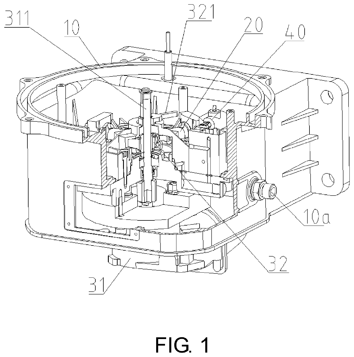
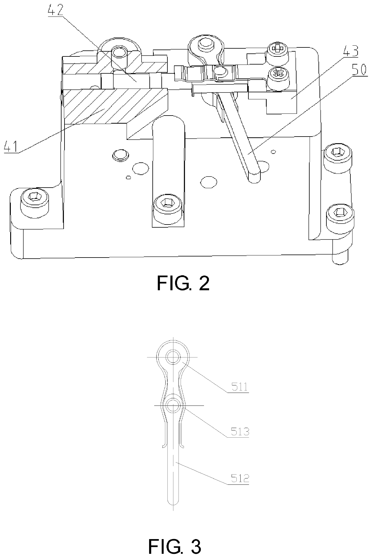
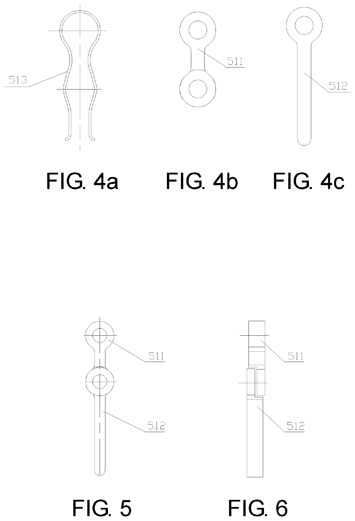
[0052]Please refer to FIG. 2 to FIG. 6 for the lever mechanism 50. In the embodiment, the lever mechanism 50 includes a combined lever. The combined lever includes a first lever body 511 and a second lever body 512. The lever mechanism further includes a spring clip 513. A first end of the first lever body 511 is rotatably connected to a valve body 41 of the two-position reversing valve 40; specifically, they can be connected by means of a pin. A second end of the first lever body 511 is hinged with a first end of the second lever body 512. Moreover, an outer end of the valve core 42 is hinged with the second end of the first lever body 511. Specifically, a through hole may be disposed at the second end of the first lever body 511, the first end of the second lever body 512, and the outer end of the valve core 42, and those three ends can be connected through a pin.

[0053]The first lever body 511 and the second lever body 512 are sandwiched in the spring clip 513. As shown in FIG. 3,...

embodiment 3

[0075]Please refer to FIG. 12 for the lever mechanism 50. In this embodiment, the lever mechanism 50 includes a swing arm 531. A first end of the swing arm 531 is rotatably connected to the valve body 41 of the two-position reversing valve 40. A middle part of the swing arm 531 is connected to the valve core 42. After assembly, under the effect of external force, the swing arm 531 can rotate around its first end, and the swing arm 531 can pull the valve core 42 to move during the rotation process, thereby changing the position of the valve core 42. Similarly, in order to prevent the valve core 42 from moving excessively, the corresponding position on the valve body 41 is also provided with the position-limiting member 43 that limits the position of the valve core 42. In this embodiment, the toggle member 532 provided on the output rotating shaft 311 is an elastic structure. When the output rotating shaft 311 rotates, a second end of the swing arm 531 is pushed by the elastic toggle ...

embodiment 5

[0083]the lever mechanism 50 is shown in FIG. 16. In this embodiment, the lever mechanism 50 includes a swing arm 511, a rotation arm 512, and a spring clip 513. A first end of the swing arm 511 is hinged to the valve core 42. A middle part of the swing arm 511 is rotatably connected to the valve body 41 of the two-position reversing valve 40; specifically, they can be connected by a pin. A second end of the swing arm 511 is hinged to a first end of the rotation arm 512. Specifically, a through hole may be disposed at the second end of the swing arm 511 and the first end of the rotation arm 512, and the two are connected by a pin. The swing arm 511 and the rotation arm 512 are sandwiched in the spring clip 513.

[0084]After assembling as above, under the effect of external force, the swing arm 511 can rotate around its middle part, and the swing arm 511 can pull the valve core 42 to move during the rotation process, thereby changing the position of the valve core 42. When the rotation...


PUM


Abstract

A grease pumping device includes a pump body, a driving mechanism, a plunger pair, a reversing valve and a lever mechanism. A switching action between each valve position of a valve core of the reversing valve is driven by the lever mechanism. An output rotating shaft drives a toggle member rotating therewith, and when the output rotating shaft rotates reciprocally in forward and reverse directions, the toggle member toggles the lever mechanism in the forward and reverse directions, such that the lever mechanism swings reciprocally. At least one of the lever mechanism and the toggle member is an elastic structure, when the output rotating shaft rotates, the toggle member contacts the lever mechanism and drives the valve core to operate, when the valve core is switched to a corresponding valve position, the toggle member and the lever mechanism slide relatively by elastic deformation of the elastic structure.

Description

CROSS-REFERENCE TO RELATED APPLICATION[0001]This is a continuation-in-part application of International Application No. PCT / CN2018 / 108859, filed on Sep. 29, 2018, which claims the priority benefits of China Application No. 201711016253.8, filed on Oct. 25, 2017. The entirety of each of the above-mentioned patent applications is hereby incorporated by reference herein and made a part of this specification.BACKGROUNDTechnical Field[0002]The invention relates to a grease pumping device for injecting lubricating grease into a bearing, and belongs to the field of grease lubrication.Description of Related Art[0003]The centralized lubrication system is commonly utilized in many industries such as large-scale construction machinery, military machinery, long-distance automatic production lines, and outdoor working vehicles and machinery in alpine regions. Centralized lubrication systems usually adopt a grease pumping device to pump lubricating grease to the grease dispenser, which is then tr...

Claims


Application Information

Patent Timeline
IPC IPC(8): F16N13/10F16N23/00
CPCF16N13/10F16N23/00F16N13/02F16N11/08F16K31/523
Inventor ZHAO, DAPINGLIU, XINGONGLIU, ZHANGMA, LIFENG
Owner AUTOL TECH
Why Eureka
Try Eureka