
Handling device for repositioning parts

a technology for repositioning parts and handling devices, which is applied in the direction of lifting devices, conveyor parts, load-engaging elements, etc., can solve the problems of unsuitability of known handling devices for this purpose and consequent unsuitability of devices for changing, and achieve the effect of facilitating the chang

Inactive Publication Date: 2004-10-07
FESTO AG & CO KG
View PDF1 Cites 16 Cited by
  • Summary
  • Abstract
  • Description
  • Claims
  • Application Information

AI Technical Summary

Benefits of technology

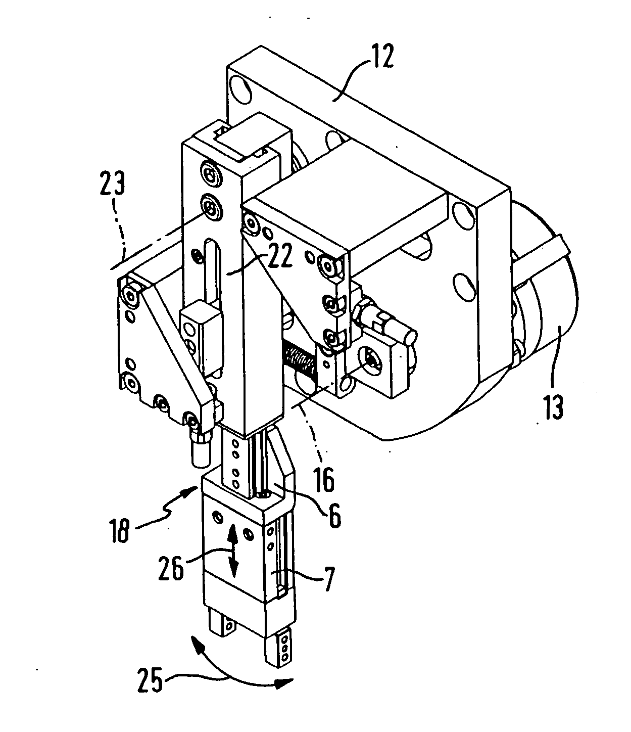
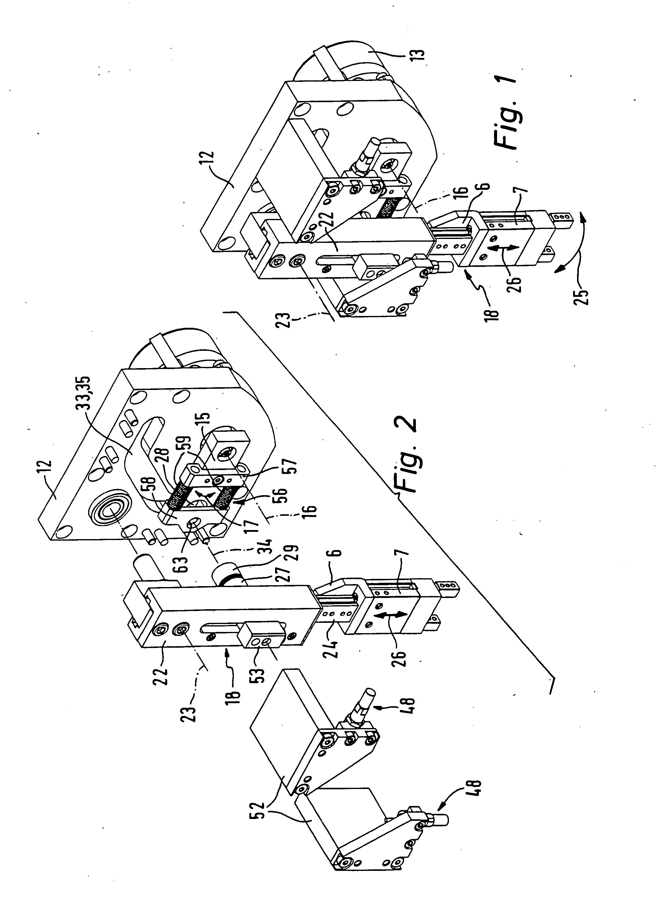
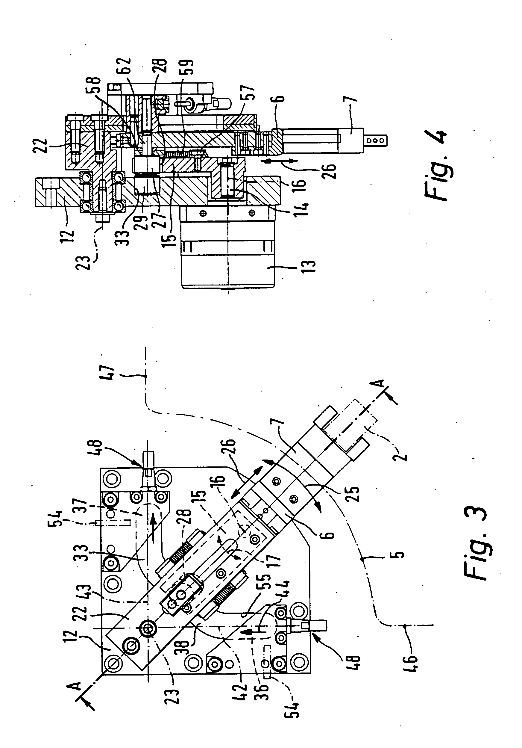
[0015] In the case of a particularly expedient design the handling part is a component of a pivotally movable handling arm, which in addition to the handling part also has a bearing part. For the location of the second pivot axis the bearing part is pivotally mounted in a stationary manner, the handling part being guided in an adjustable fashion of the bearing part in an exclusively linear manner in order to define the axis of the linear stroke movement. The pivotal movements occurring on the handling path are accordingly in all performed by the handling arm, whereas the linear movements defined by the two linear terminal sections of the path setting cam are exclusively performed by the handling part in relation to the stationary bearing part. Owing to this decoupling a separate design of the pivotal bearing means and of the linear guide means is possible, something which ensures a high degree of accuracy and only minimum wear.
[0017] More particularly when parts with large masses are to be repositioned or a gripper to be mounted on the handling part is relatively heavy, a design of the handling device is recommended, in the case of which the two pivot axes are on the same side of the path setting cam, the first pivot axis being mounted between the path setting cam and the second pivot axis. The first pivot axis may in this case be more or less completely surrounded by the path setting cam, the second pivot axis being placed in the open region of the path setting cam between the two linear terminal sections. The leverage then tends to be more convenient in this that is to say than with the previously mentioned one, although however a relatively longer path setting cam is necessary so that the pivot arm as well is pivoted during a handling cycle through a larger pivot angle.

Problems solved by technology

The known handling device is unsuitable for this purpose.
The device is consequently unsuitable for changing the alignment of a part to be repositioned during a repositioning operation through an angle of for example 90.degree..

Method used


Image

  • Handling device for repositioning parts
  • Handling device for repositioning parts
  • Handling device for repositioning parts

Examples


Embodiment Construction

[0033] The designs of the handling device in accordance with the invention illustrated in drawings respectively render possible a sequential repositioning of parts of any desired type, and more particularly of small parts such as screws, bolts or other parts having a certain longitudinal extent in the drawing such a part to be repositioned is indicated at 2 in chained lines.

[0034] Such handling devices are so designed that the part 2 is able to be shifted during a repositioning operation between a first end position 3 indicated in FIGS. 5 and 16 and a second end position 4 indicated in FIGS. 11 and 20, the curve of its movement corresponding to the course of a handling path 5 being marked in chained lines in FIGS. 3 and 14 as followed by a driven handling part 6, which is fitted with a gripper 7, of some suitable type, serving for releasable holding the part 2 to be repositioned.

[0035] The gripper 7 may for example be a tongs-like gripper, which has pivoting jaws or jaws moved paral...


PUM


Abstract

A handling device for repositioning parts having a pivot arm able to be pivoted about a first pivot axis and a handling part adapted to bear a gripper and able to be pivoted with respect to a second pivot axis. The handling part is furthermore carried so that it may be radially moved in relation to the second pivot axis and cooperate by way of a cam follower with a path setting cam having two linear terminal sections. During operation of the device the handling part may move along a handling path, which has two linear terminal sections.

Description

BACKGROUND OF THE INVENTION.[0001] The invention relates to a handling device for the repositioning of parts comprising a pivot arm able to be driven by a drive means to perform an oscillating movement about a stationary first pivot axis, a handling part serving for carrying a gripper, which while performing a second pivot movement about a stationary second pivot axis is able to be pivoted and furthermore is able to be set radially in relation to the second pivot axis while performing a linear or straight stroke.THE PRIOR ART[0002] A handling device disclosed in the German patent publication (utility model) 29,618,418 of this type is utilized for repositioning parts, which are taken up at a first position and shifted to a second position where they are put down after being reorientated through 90.degree.. The respective part to be repositioned is held by a gripper during the repositioning operation, and such gripper is seated on a moving handling part of the handling device and toge...

Claims


Application Information

Patent Timeline
IPC IPC(8): B65G47/90
CPCB65G47/904
Inventor FEYRER, THOMASTHORWART, GERHARDARMBRUSTER, RAINER
Owner FESTO AG & CO KG
Learn More