
Wireless communication system and image forming device

a communication system and wireless technology, applied in the direction of near-field systems using receivers, instruments, electrographic processes, etc., can solve the problems of device malfunction, device malfunction, image quality degradation,

Inactive Publication Date: 2004-10-14
FUJIFILM BUSINESS INNOVATION CORP
View PDF20 Cites 44 Cited by
  • Summary
  • Abstract
  • Description
  • Claims
  • Application Information

AI Technical Summary

Benefits of technology

[0011] In view of the aforementioned, an object of the present invention is to provide a wireless communication system in which a common structure and configuration are used for tag attaching portions at cartridge parts which are loaded into respectively different cartridge loading portions, and in which it is easy to adjust the positions of the wireless communication tags at the cartridge parts to positions which are suited for communication with respect to main body antennas, and to provide an image forming device to which this wireless communication system is applied.
[0011] In view of the aforementioned, an object of the present invention is to provide a wireless communication system in which a common structure and configuration are used for tag attaching portions at cartridge parts which are loaded into respectively different cartridge loading portions, and in which it is easy to adjust the positions of the wireless communication tags at the cartridge parts to positions which are suited for communication with respect to main body antennas, and to provide an image forming device to which this wireless communication system is applied.
[0011] In view of the aforementioned, an object of the present invention is to provide a wireless communication system in which a common structure and configuration are used for tag attaching portions at cartridge parts which are loaded into respectively different cartridge loading portions, and in which it is easy to adjust the positions of the wireless communication tags at the cartridge parts to positions which are suited for communication with respect to main body antennas, and to provide an image forming device to which this wireless communication system is applied.

Problems solved by technology

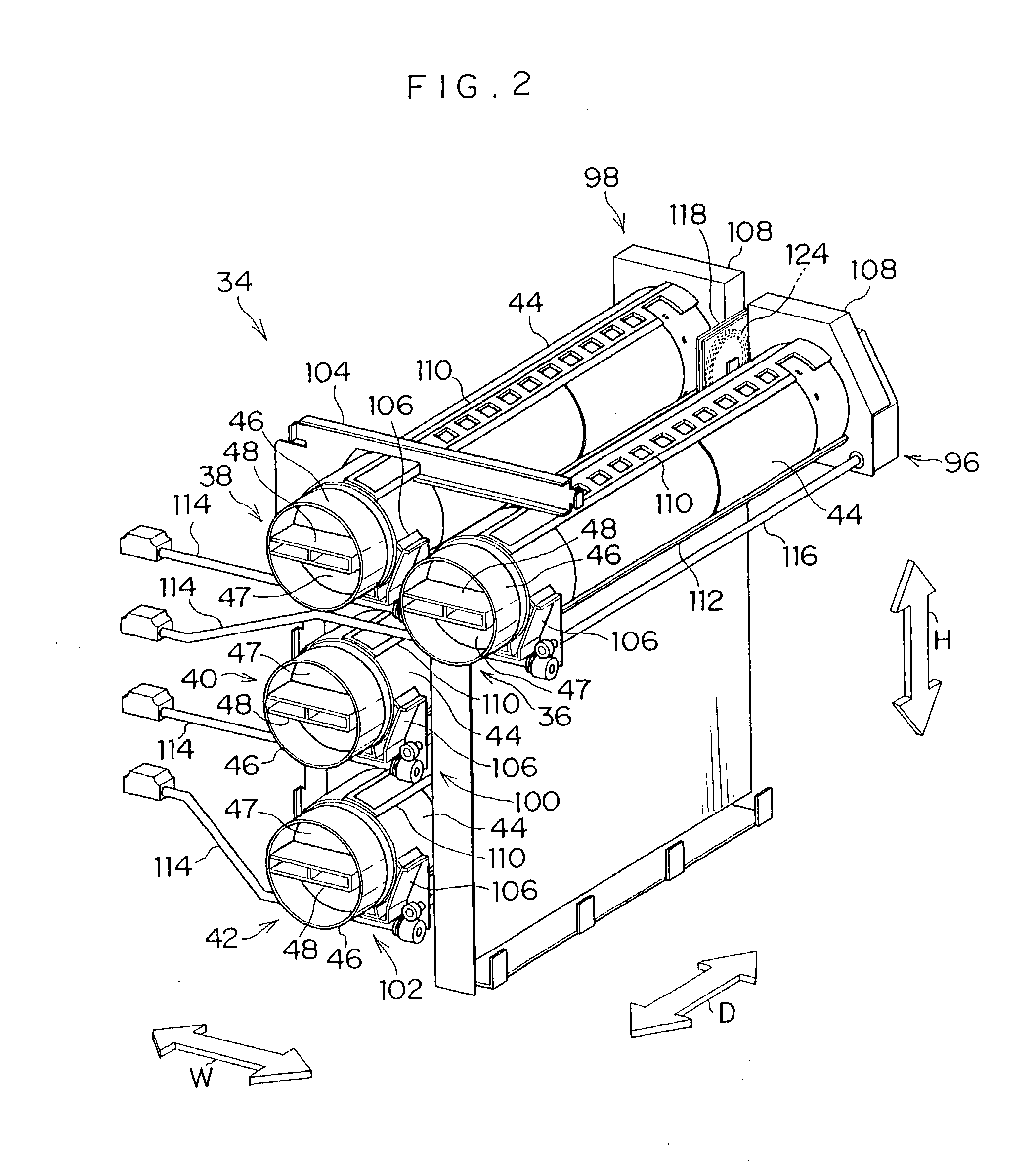
Accordingly, in plural types (e.g., four types) of toner cartridges loaded in an image forming device which can form color images, the attaching portions for the wireless communication tags (tag attaching portions) must be made to have a different shape and a different structure for each type of toner cartridge, and it is difficult to use a common configuration and structure for the tag attaching portions.
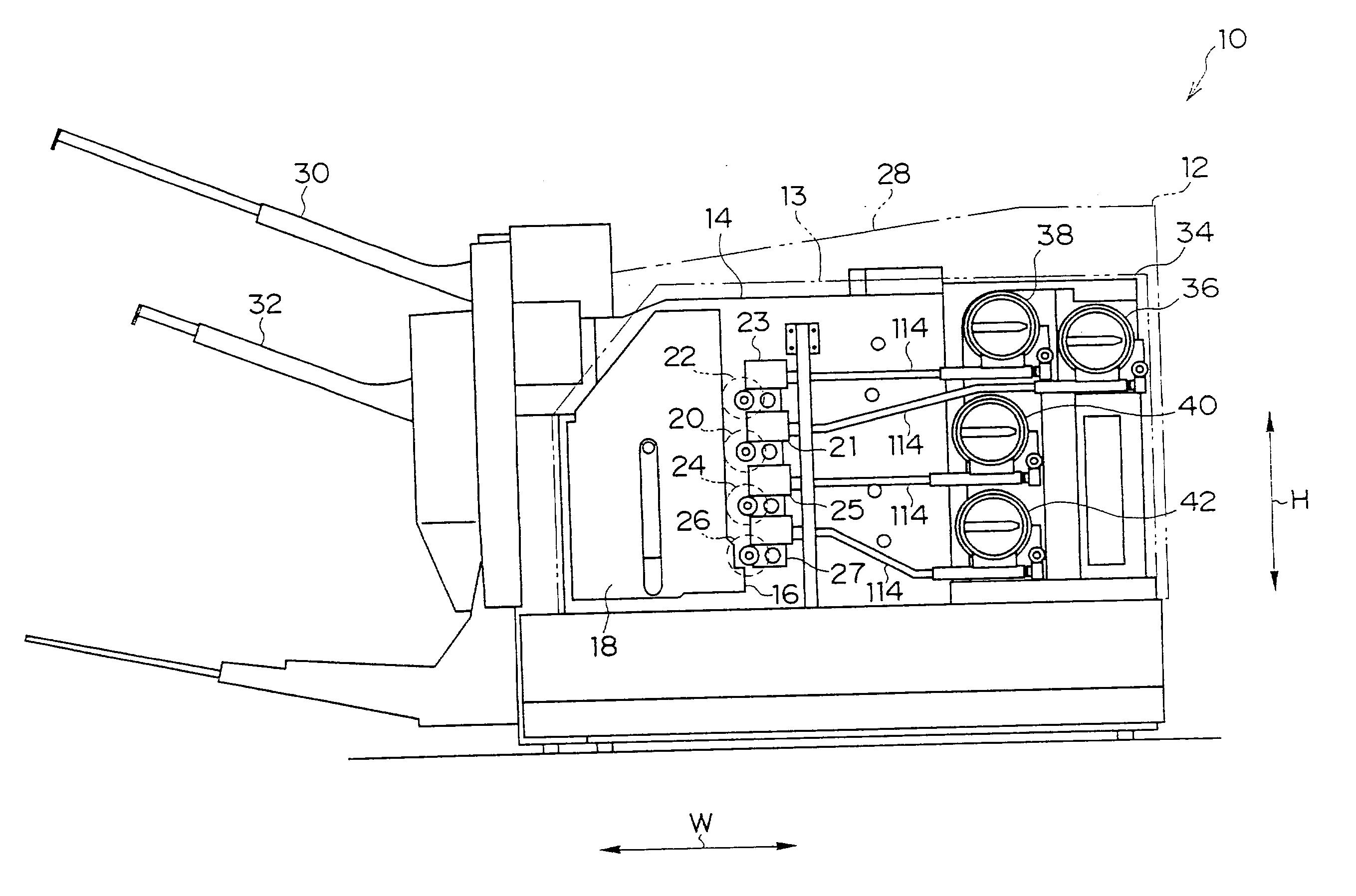
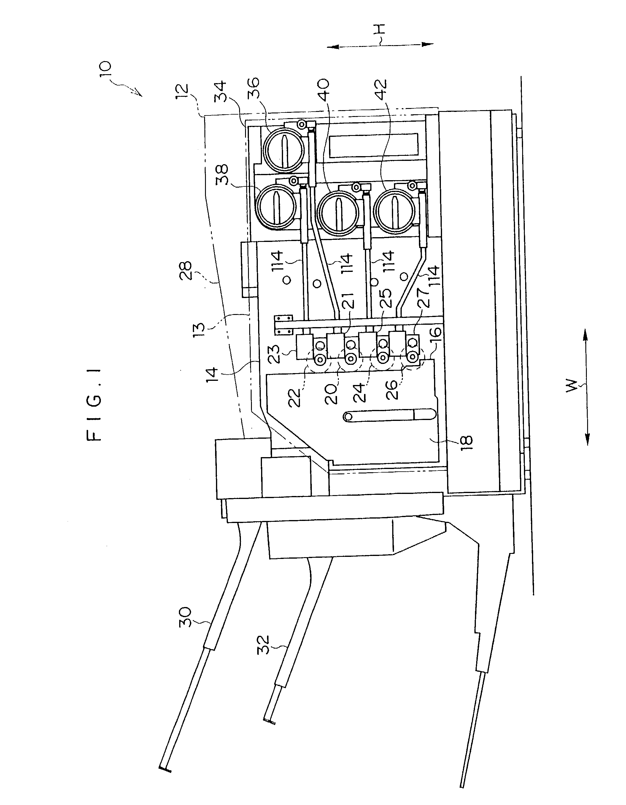
When the toner cartridges 36, 38, 40, 42 which have been recycled by irregular dealers are loaded in the laser printer 10, there is the concern that problems may arise such as the device will malfunction, the image quality will deteriorate, or the like.

Method used


Image

  • Wireless communication system and image forming device
  • Wireless communication system and image forming device
  • Wireless communication system and image forming device

Examples


Embodiment Construction

[0096] Next, first and second modified examples of the toner cartridge in the wireless communication system relating to the embodiment of the present invention will be described. Note that the portions of the toner cartridges relating to these modified examples, which are other than the wireless communication tags 72 and the attaching portions thereof, have the same structures as in the toner cartridges 36, 38, 40, 42 (see FIG. 4) which were previously described. Thus, members of the toner cartridges relating to the modified examples, which members have structures and operations which are the same as in the toner cartridges 36, 38, 40, 42, are denoted by the same reference numerals, and description thereof is omitted.

[0097] FIG. 12 illustrates a first modified example of the toner cartridge of the wireless communication system relating to the embodiment of the present invention. A toner cartridge 200 is provided with a tag affixing portion 202 at the outer peripheral surface of the ...


PUM


Abstract

Tag attaching portions at cartridge parts which are loaded into different cartridge loading portions have common structures and configurations. A position of a wireless communication tag at the cartridge part is easily adjusted to a position suited for communication with a main body antenna. In a laser printer, accommodating chambers and accommodating portions are provided at plural regions of toner cartridges. The wireless communication tag is selectively inserted and fit into one of the accommodating chambers and accommodating portions, in accordance with a position of the cartridge loading portion in which the toner cartridge is loaded. In this way, in a state in which the toner cartridges are respectively loaded in the cartridge loading portions, the wireless communication tags are substantially parallel to and sufficiently close to the main body antennas of antenna units.

Description

[0001] 1. Field of the Invention[0002] The present invention relates to a wireless communication system which can be applied to various types of devices in which plural cartridge parts can be removably loaded in a device main body, and to an image forming device (such as a copier, a facsimile machine, a printer or the like) in which plural cartridge parts can be removably loaded in a device main body.[0003] 2. Description of the Related Art[0004] Among image forming devices using an electrophotographic process such as a copier, a laser printer or the like, there are image forming devices in which the container which houses toner is structured as a toner cartridge in order to facilitate maintenance of the device. In such an image forming device, when all of the toner has been discharged from the interior of the toner cartridge, the user replaces the toner cartridge with a new one so as to replenish the toner. At this time, in most cases, the used toner cartridge which has been remove...

Claims


Application Information

Patent Timeline
IPC IPC(8): G03G21/00B41J2/175G03G15/00G03G15/08G03G21/16H04B5/02H04N1/00
CPCB41J2/17546G03G15/553G03G15/55G03G15/0855G03G15/0872G03G15/0865G03G15/0863
Inventor HARUMOTO, KATSUMI
Owner FUJIFILM BUSINESS INNOVATION CORP
Learn More