

Three-dimensional image evaluation unit and display device using the unit
a three-dimensional image and display device technology, applied in image enhancement, television systems, instruments, etc., can solve the problems of hard to see and likely not to function well according to images, and achieve the effect of rapid change of parallax
- Summary
- Abstract
- Description
- Claims
- Application Information
AI Technical Summary
Benefits of technology
Problems solved by technology
Method used
Image

Examples
first embodiment
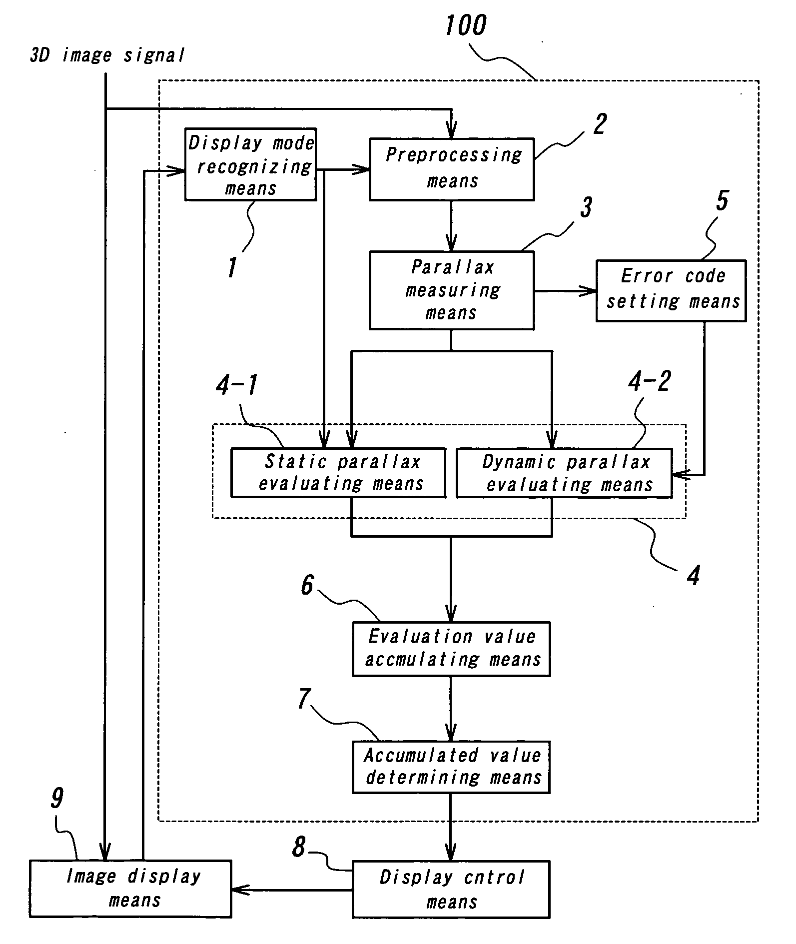
[0036] FIG. 1 is a block diagram showing the structure of a display device according to the present invention. The display device has a three-dimensional image evaluation device 100, a display control means 8, and an image display means 9, Three-dimensional image evaluation device 100 comprises a display mode recognizing means 1, a preprocessing means 2, a parallax measuring means 3, an evaluating means 4, an error code setting means 5, an evaluation value accumulating means 6, and an accumulated value determining means 7, The evaluating means 4 has a static parallax evaluating means 4-1 and a dynamic parallax evaluating means 4-2.
[0037] In FIG. 1, the three-dimensional image signal is inputted to an image display means 9 to display the three-dimensional image. Here, three-dimensional image signals are video signals for the game machine, the video device or computers, or the like, As such signals, there are signals in which right and left images are alternately transmitted every fie...
second embodiment
[0081] FIG. 12 is a flow chart for explaining the operation of the principal portion in the second embodiment of the display device according to the present invention. In the present embodiment, the dynamic parallax evaluation method in the dynamic parallax evaluating means 4-2 shown in the first embodiment, is different. That is, in the first embodiment, if parallax changes are larger than reference values in every one measuring the evaluation value is set but, the present embodiment pays attention to particularly, the negative parallax change, that is, the change in direction dashing out from screen to viewer and the amount of dashing out thereof.
[0082] Therefore, the dynamic parallax evaluation method according to the present embodiment comprises a step S71 of taking the difference .DELTA.X(n) between n-th parallax statistic and n-1th parallax statistic, a step S72 of deciding whether or not .DELTA.X(n) is smaller than the specified value, a step S73 of setting the parallax chang...
third embodiment
[0085] FIG. 13 is a flow chart for explaining the operation of the principal portion in the third embodiment of the display device according to the present invention. Even in the present embodiment, the dynamic parallax evaluation method in the dynamic parallax evaluating means 4-2 shown in the first embodiment, is different, so that the display device according to the present embodiment comprises a step S81 of taking the difference .DELTA.X(n) between n-th parallax statistic and n-1th parallax statistic, a step S82 of obtaining the accumulated parallax variation MX by accumulating the parallax variation, a step S83 of deciding whether or not the accumulated parallax variation is smaller than the specified value, a step S84 of setting the parallax change evaluation value MP, a step S85 of resetting the accumulation parallax variation MX, and a step S86 of setting the parallax change evaluation value MP to 0.
[0086] That is, in the first and second embodiments, the parallax change is ...
PUM
 Abstract
Description
Claims
Application Information