
Wavelength-division multiplex communication system and apparatus

a communication system and multiplex technology, applied in multiplex communication, transmission monitoring, electromagnetic repeaters, etc., can solve the problems of affecting transmission efficiency, and the apparatus is unable to recognize how much traffic each channel bears

Inactive Publication Date: 2004-10-28
FUJITSU LTD
View PDF8 Cites 32 Cited by
  • Summary
  • Abstract
  • Description
  • Claims
  • Application Information

AI Technical Summary

Problems solved by technology

Further, since the WDM communication apparatus (terminal 200 (400) or repeater station 300) combines optical channels at separate wavelengths into WDM signals, increase in line traffic on a specific channel causes access congestion in the channel, thus impairing the transmission efficiency.
As is evident from FIGS. 28 and 29, however, since the WDM communication apparatus itself never converts light signals into electric form, it is impossible for the apparatus to recognize how much traffic the individual channels bear.

Method used


Image

  • Wavelength-division multiplex communication system and apparatus
  • Wavelength-division multiplex communication system and apparatus
  • Wavelength-division multiplex communication system and apparatus

Examples


Embodiment Construction

)

[0078] One preferred embodiment of the present invention will now be described with reference to the accompanying relevant drawings.

[0079] (A) WDM Communication System:

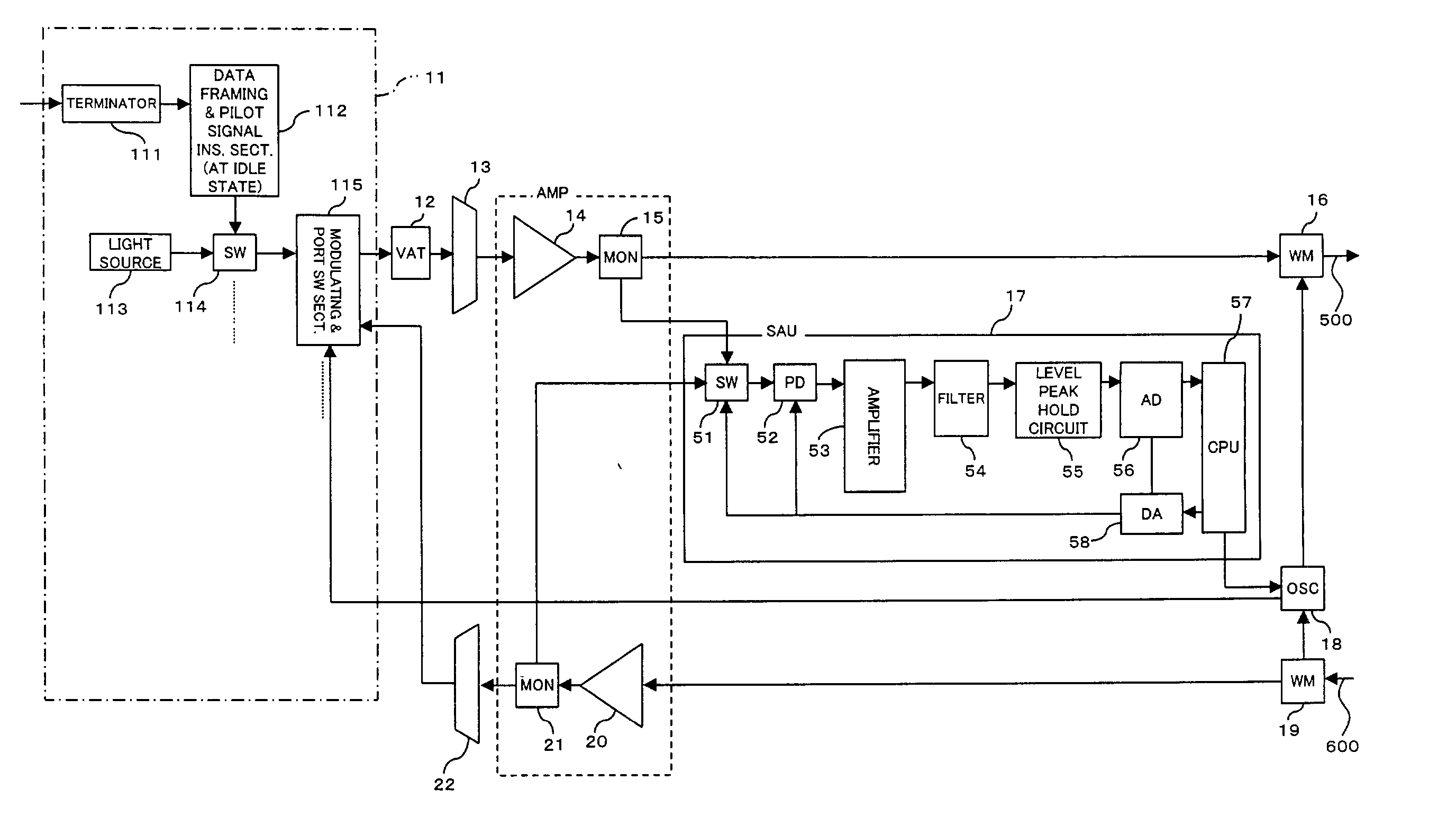
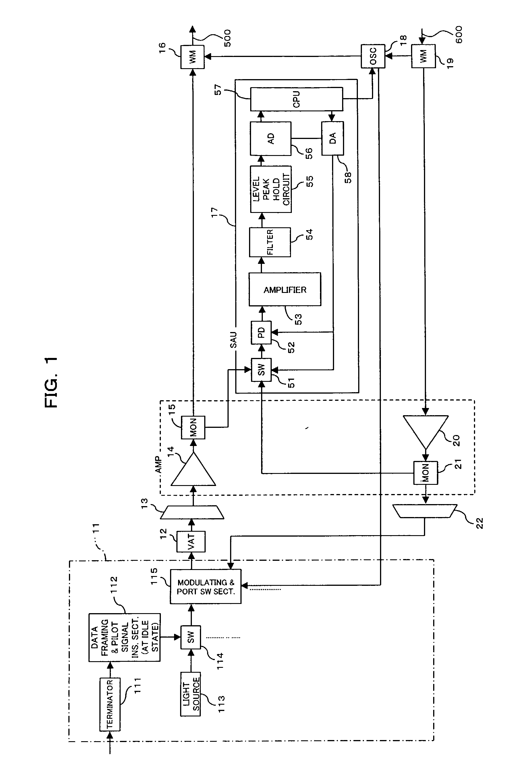
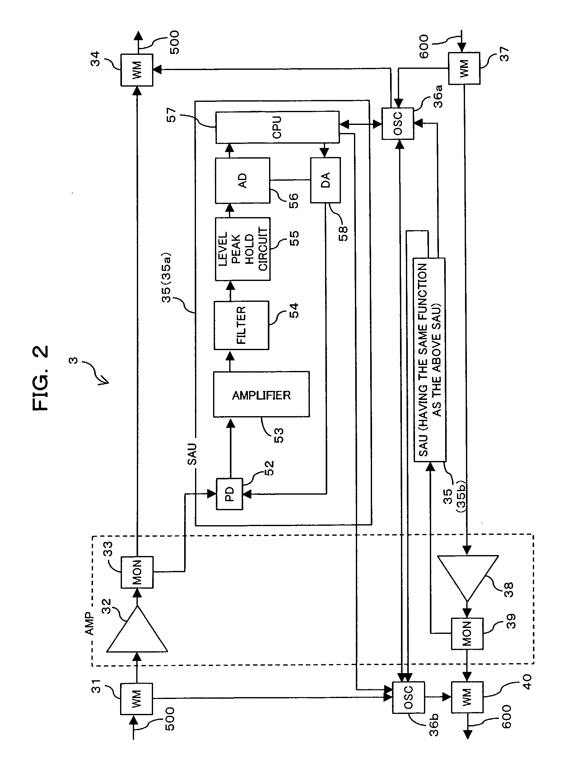
[0080] FIG. 1 shows a construction of terminal equipment for use in a wavelength-division multiplex (WDM) communication system according to a first embodiment of the present invention, and FIG. 2 shows a construction of a repeater station for use in the WDM communication system. Terminal equipment (hereinafter also simply called "terminal") 1 is equivalent to terminal equipment 200 and 400 of FIG. 27, and a repeater station 3 is equivalent to a repeater station 300 of FIG. 27. As in the prior art, the terminal equipment 1 and the repeater station 3 are interconnected to one another across an optical transmission path 500, 600, in the present embodiment.

[0081] Referring now to FIG. 1, terminal 1 of the present embodiment has a transponder (transceiver section) 11; variable optical attenuators 12, one for each WDM chan...


PUM


Abstract

In the WDM communication system, in the absence of data to be transmitted on an optical channel, a pilot signal transmitting means transmits the channel-unique pilot signal data on the channel. A WDM communication apparatus on a receiving end detects the pilot signal data in the received WDM signals, and on the basis of the detection result, it evaluates whether each channel is used or not. It is thus easy to recognize which channel is unused (idle) of the WDM signals, so that channel resources can be used effectively according to the traffic.

Description

[0001] 1. Field of the Invention[0002] The present invention relates to a wavelength-division multiplex communication system and wavelength-division multiplex communication apparatus for use in the system.[0003] 2. Description of the Related Art[0004] FIG. 27 shows an example of an existing wavelength-division multiplex (WDM) communication system. Referring to FIG. 27, a WDM communication system 100 has terminal equipment, 200 and 400, coupled to a communication network, such as an ATM (Asynchronous Transfer Mode) network, a SONET (Synchronous Optical Network), an SDH (Synchronous Digital Hierarchy) network, or an Ethernet (a registered trademark of Xerox Corporation), and an optical repeater 300 which is disposed between the terminal equipment, 200 and 400, and is coupled to them through an optical transmission path (an optical fiber such as a SMF (Single Mode Fiber)), 500 and 600. The optical repeater 300 amplifies and relays WDM signals bi-directionally transmitted over the optic...

Claims


Application Information

Patent Timeline
IPC IPC(8): H04B10/077H04B10/29H04B10/07H04B17/00H04J14/00H04J14/02
CPCH04B10/0775H04B2210/072H04B2210/075H04B2210/08H04J14/0221H04J14/0227H04J14/0278H04J14/0241H04B2210/074
Inventor TAKANASHI, TAKAKOIZUMI, FUTOSHI
Owner FUJITSU LTD
Learn More