Elastomeric traction band with lug reinforcements

Inactive Publication Date: 2004-11-11
SOUCY INT
View PDF14 Cites 28 Cited by
  • Summary
  • Abstract
  • Description
  • Claims
  • Application Information

AI Technical Summary

Benefits of technology

0016] Lug reinforcements help to laterally stabilize the wheels/traction band assembly as the traction band rotates. The guide lugs lateral deformation by the wheels is reduced and preferably prevented by the lug r

Problems solved by technology

The wear and the use of the traction band under extreme conditions, like high lateral loads, sometimes initiates de-tracking

Method used


Image

  • Elastomeric traction band with lug reinforcements
  • Elastomeric traction band with lug reinforcements
  • Elastomeric traction band with lug reinforcements

Examples


Example

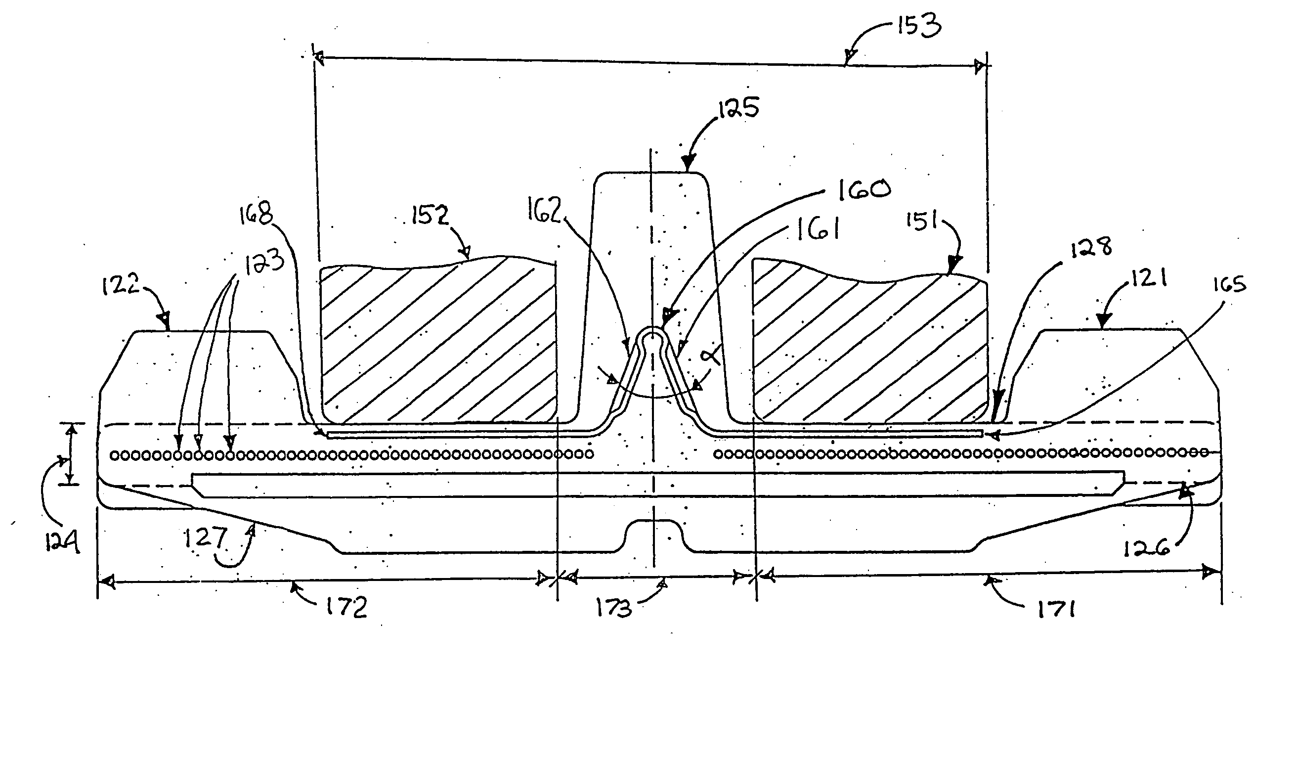
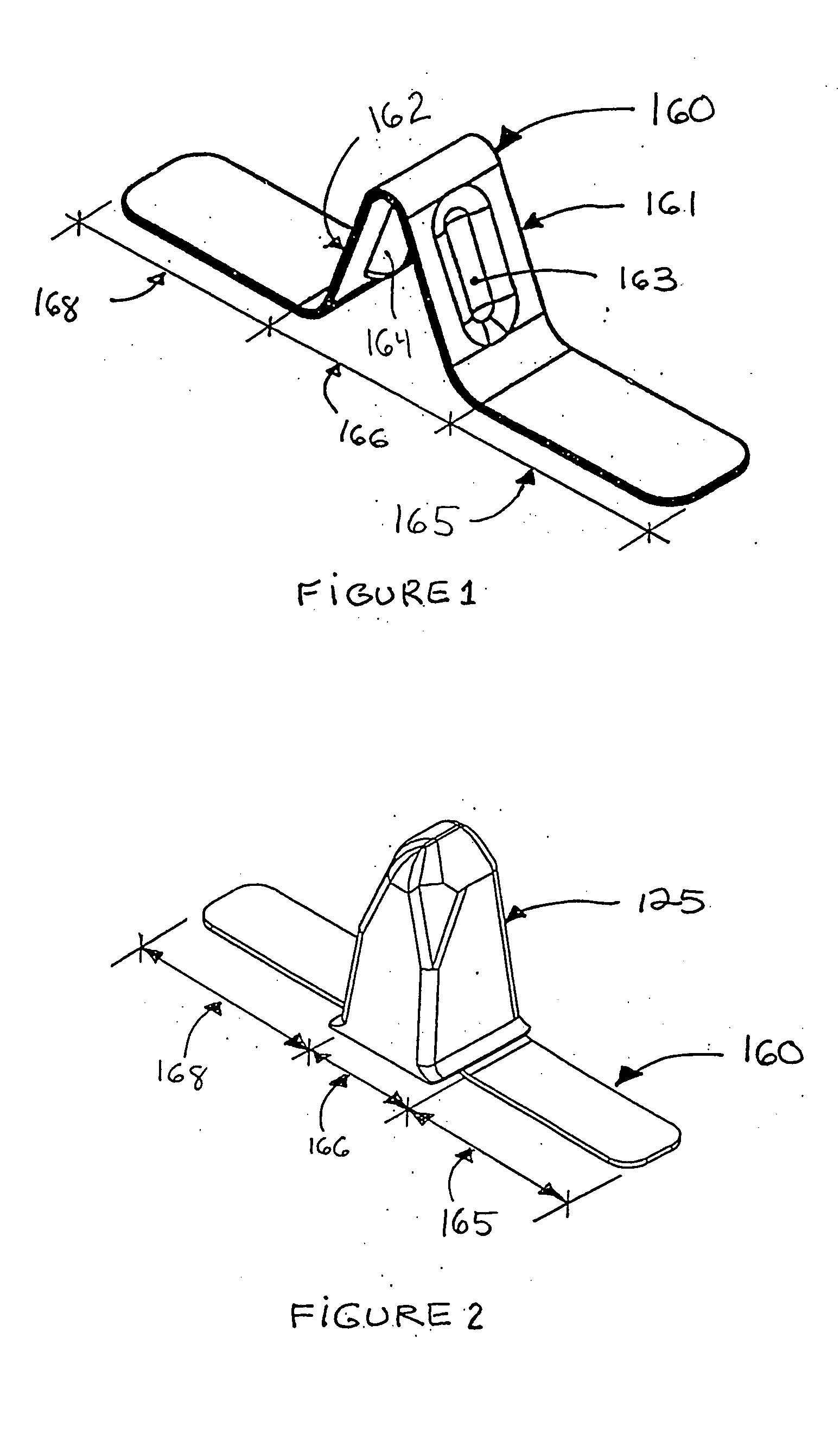
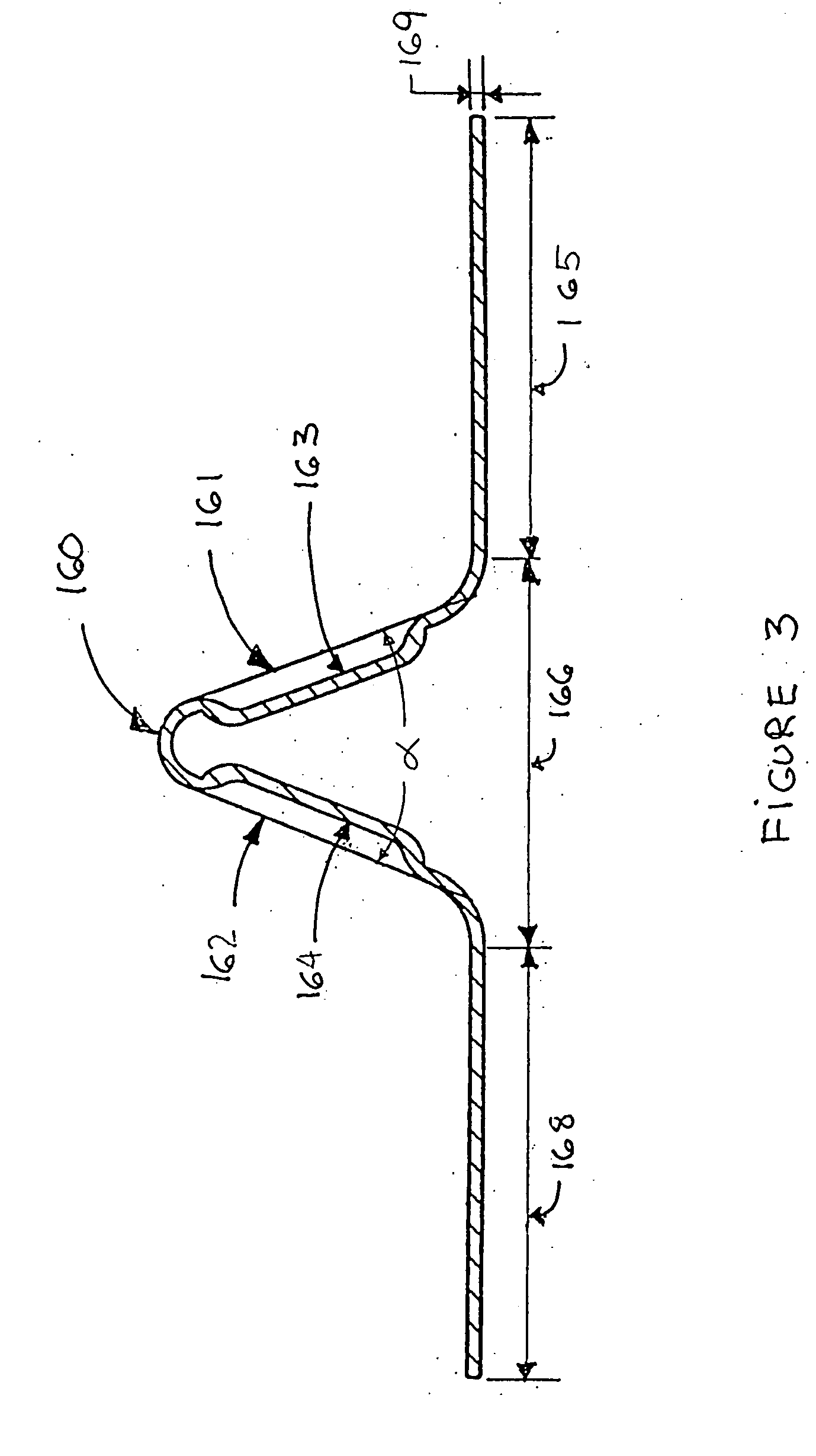
[0049] In the second embodiment shown in FIG. 8, lug reinforcements 260 are embedded in each pitch 275 of the traction band. A lug reinforcement 260 comprises a reinforcing portion 266, mainly located in the guide lug 225 and two stabilizing portions (265,268), each embedded in the band 220 and mostly between the drive lug (221,222) and the guide lug 225. The reinforcing portion 266 has inclined planar areas (261,262), with or without embossings (263,264). The inclined planar areas (261,262) extend in a longitudinal direction, connect to each other at an angle .alpha.. (not shown) and are contained within the volume of a guide lug 225. The stabilizing portions (265,268) may be provided with two arms (265a,265b and 268a,268b) in a V-shaped configuration which offers a wider and more stable section of the stabilizing portion (265,268) under the wheels.

Example

[0050] FIG. 9 illustrates a third embodiment of the invention, where each pitch 375 of the traction band 320 comprises a lug reinforcement 360 having a reinforcing portion 366 and two stabilizing portions (365,368) on each side of the reinforcing portion 366. Each stabilizing portion (365,368) is embedded in the band body 324, mostly in-between the drive lug (321,322) and the guide lug 325. The reinforcing portion 366 is made of two longitudinally extending inclined planar areas (361,362), connected to each other at an angle .alpha.. In this embodiment, each inclined planar area (361,362) has a longitudinally variable width in order to occupy, and therefore reinforce, most of the volume of the guide lugs 325.

Example

[0051] A fourth embodiment is described in FIG. 10. In each pitch 475 of the traction band 420, a lug reinforcement 460 is made of a selected number of cords or rods 455. Each cords or rods 455 have a lateral bi-dimensional profile comprising a reinforcing portion 466 and a pair of stabilizing portion (465,468) located on each side of the reinforcing portion 466. The reinforcing portion 466 is mainly located in the guide lug 425 and the longitudinal juxtaposition of each cords or rods 455 defines two inclined planar areas (461,462) at an angle .alpha. (not shown). The stabilizing portions (465,468) are embedded in the band body 424, mostly located between the drive lug (421,422) and the guide lug 425.

[0052] As seen in FIG. 4 and 5, the use of lug reinforcements 160 in a traction band 120 significantly reduces de-tracking events by reducing the deformation of the elastomeric material in the guide lugs 125. This phenomenon is firstly explained by the stabilizing portions (165,168) bei...


PUM


Abstract

This invention relates to an endless elastomeric traction band that is used to propel tracked vehicles [i.e., vehicles which use endless traction bands rather than tires to contact the terrain over which they are driven, e.g., tractors, tanks, bulldozers, etc.] and, more particularly, to the inner surface of such a traction band where lug reinforcements are inserted to laterally reinforce the guide lugs and minimize de-tracking occurrences.

Description

[0001] This invention relates to an endless traction band that is used to propel tracked vehicles comprising guide lugs on its inner surface where lug reinforcements are inserted to laterally reinforce the guide lugs.[0002] Numerous types of vehicles are frequently used on terrain where it is difficult for pneumatic tires to operate. Both defense vehicles, such as tanks and amphibious vehicles, and civilian vehicles, such as tractors and recreational vehicles, are sometimes utilized on terrains which are very soft, for example sand surfaces. Pneumatic tires are not capable of efficient operations on such soft surfaces, as they tend to burrow into the surface, rather than riding across it.[0003] In the past, the most popular type of traction band for heavy duty vehicles have been those having metallic traction surfaces.[0004] Recently, elastomeric endless traction bands have become popular due to an increase in construction, and in urban areas, where vehicles having traction bands mu...

Claims


Application Information

Patent Timeline
IPC IPC(8): B62D55/24
CPCB62D55/244
Inventor SOUCY, GILLESDELISLE, MARCDELAND, ANDRE
Owner SOUCY INT
Why Eureka
Try Eureka