Infrared sight glass for aftermarket fitment

a technology of infrared sight glass and aftermarket fittings, which is applied in the direction of optical elements, electromagnetic radiation sensing, instruments, etc., can solve the problems of inability to provide glass or plastic sight glass in equipment, inability to use sight glass in public places where unauthorized persons could be exposed to electric shock hazards, and inability to penetrate the enclosure of camera detection

Active Publication Date: 2004-11-18
FLUKE ELECTRONICS
View PDF8 Cites 21 Cited by
  • Summary
  • Abstract
  • Description
  • Claims
  • Application Information

AI Technical Summary

Problems solved by technology

A problem occurs when the electrical equipment is contained within an enclosure, and the infrared radiation which the camera detects is unable to penetrate the enclosure in an identifiable form.
The provision of a glass or plastic sight glass in the equipment would not solve the problem as infrared radiation cannot penetrate either of these mediums.
Infrared transparent sight glasses in the prior a

Method used


Image

  • Infrared sight glass for aftermarket fitment
  • Infrared sight glass for aftermarket fitment
  • Infrared sight glass for aftermarket fitment

Examples


Embodiment Construction

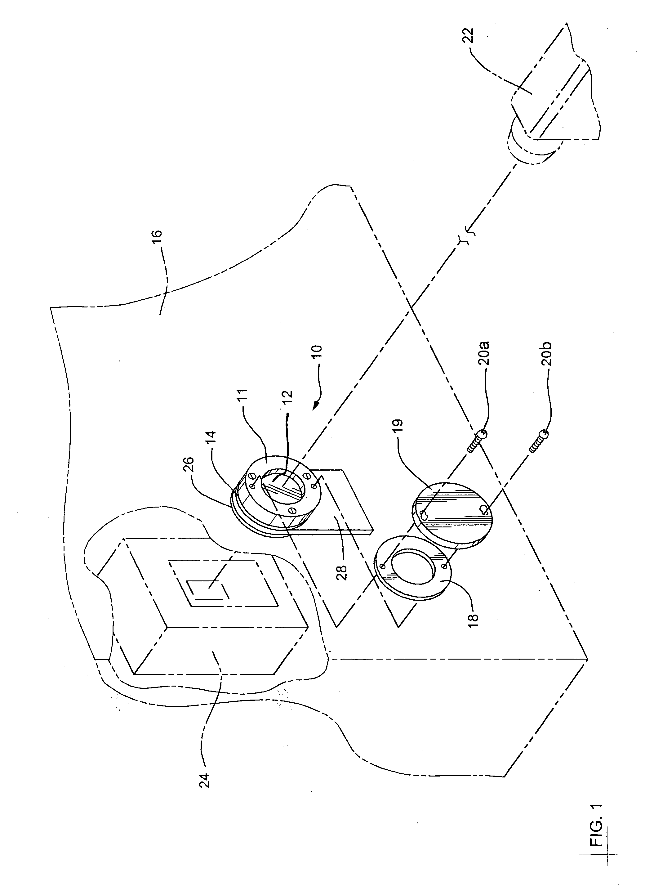
[0020] Referring to FIG. 1, a partial perspective view of an enclosure 16 is shown having electrical apparatus 24 inside which receives a voltage causing a temperature rise. On the side of the enclosure 16 is mounted an infrared sight glass 10. An infrared thermal imaging camera 22 is positioned adjacent to the infrared sight glass 10 and in the line of sight of the electrical apparatus 24 for monitoring the temperature of the electrical apparatus 24. The infrared sight glass 10 is rapidly fitted on the existing enclosure 16 from the outside without needing access to the enclosure 16 of the monitored apparatus 24. In addition, a gasket 18 and a protective security cover 19 are provided on the outside of the infrared sight glass 10.

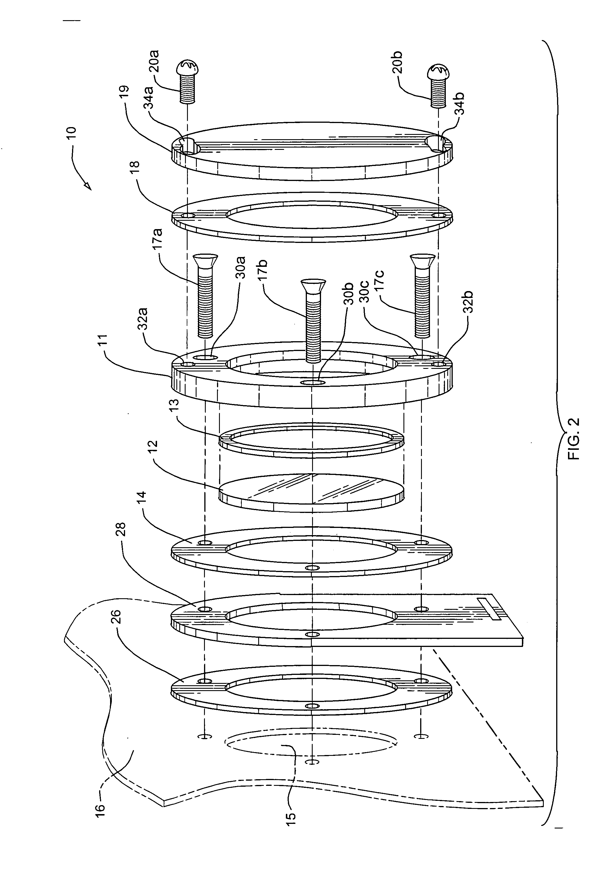
[0021] Referring to FIG. 2, an exploded view of the infrared sight glass 10 is shown according to the present invention for use on the enclosure 16 with heat generating apparatus 24 and in particular for aftermarket fitment on such enclosure 16. The enclos...


PUM


Abstract

An infrared sight glass for aftermarket fitment around an opening of an enclosure which enables thermal inspection of electrical equipment within the enclosure. The mounting of the sight glass is performed externally which avoids having to access the interior of the enclosure. The infrared sight glass comprises an infrared transmitting medium to facilitate use of an external infrared thermal imaging camera for monitoring the electrical equipment. A removable protective cover is locked into a closed position by security key screws and is easily removed by a slight twist when the key screws are loosened.

Description

[0001] This is a nonprovisional patent application claiming priority of provisional application for patent No. 60 / 319,923, filed Feb. 4, 2003.[0002] 1. Field of the Invention[0003] This invention relates to thermal inspection of electrical equipment using an infrared camera, and in particular to an infrared sight glass adapted for rapid fitment to an existing enclosure without needing access to the interior of the enclosure containing the monitored equipment.[0004] 2. Description of Related Art[0005] Thermographic inspection of electrical equipment is carried out using a specially adapted camera which registers infrared radiation and converts this to a visible image. The particular advantage is that for accurate thermographic inspections to take place, the equipment to be inspected must be under normal running conditions. A problem occurs when the electrical equipment is contained within an enclosure, and the infrared radiation which the camera detects is unable to penetrate the enc...

Claims


Application Information

Patent Timeline
IPC IPC(8): G02B7/00
CPCG02B7/007H01H2001/0021H01H2009/0292
Inventor HOLLIDAY, GRAHAM R.HOLLIDAY, ANTONY J.
Owner FLUKE ELECTRONICS
Why Eureka
Try Eureka